Assembling the Cardboard
This tutorial shows how to assembly our cardboard. You will need the parts of the cardboard before you should start this tutorial. Check hardware guide for more informations. For a PDF-version of this tutorial, check our download section.
You need:
- Velcro rubber band (female, 2x approx. 90cm)
- Velcro tape (male, 3x approx. 3cm , and female, 1x approx. 3cm)
- cord stopper (1 for each camera)
- thin rubber bands (2 for each camera)
- glue/hot glue gun
- scissor
- ruler
- biconvex acrylic lenses (2x 37mm diameter with 45mm focal length)
- USB-camera and IR-LED-board (1 or 2 each of them)
- 4-port USB-hub (approx. 8cm length and 1,1cm width)
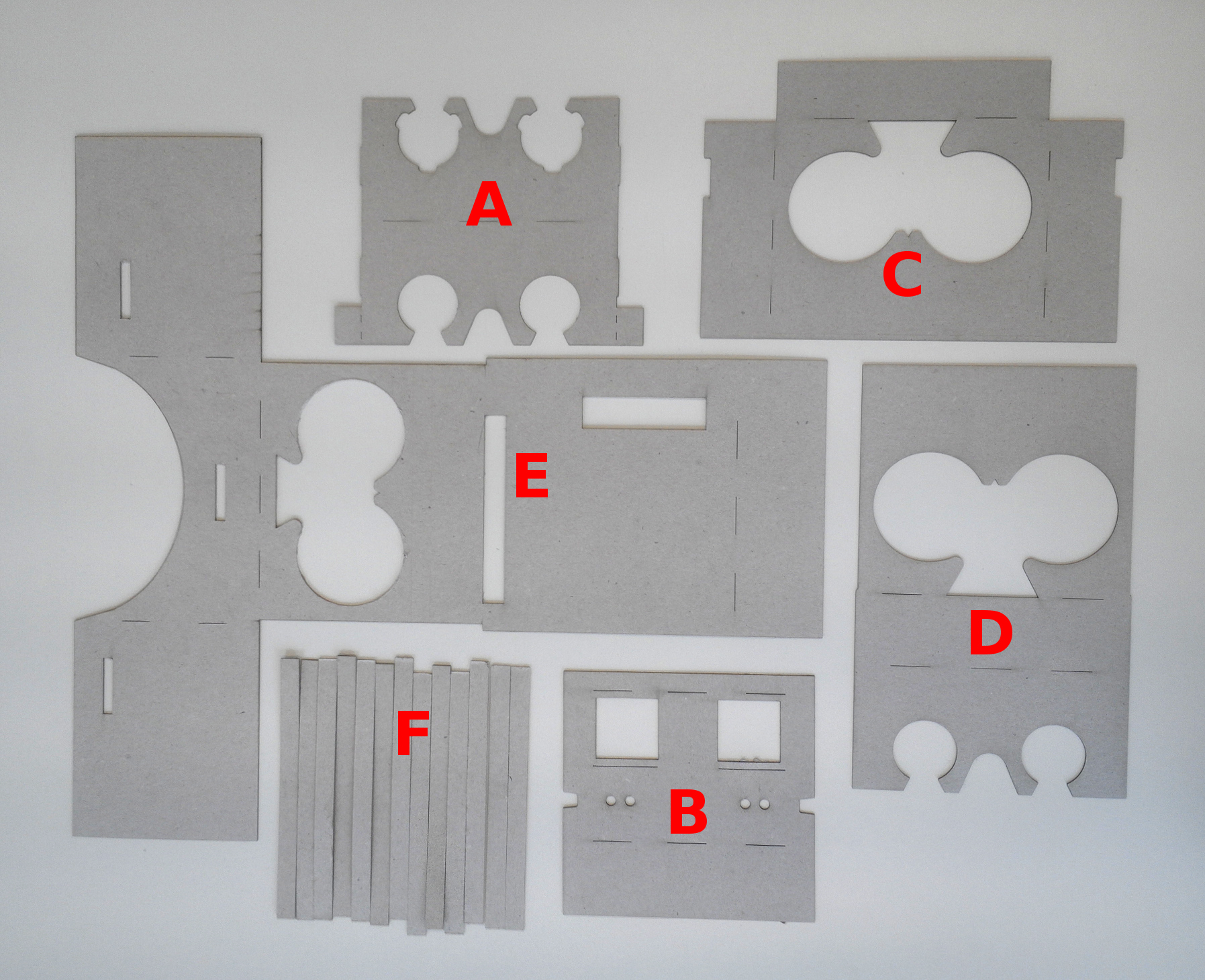
Figure 1: Cardboard pieces from A to F
-
- Lay the previously cut parts in front of you (see figure 1). You should have five individual parts (A to E) and six times the part F.
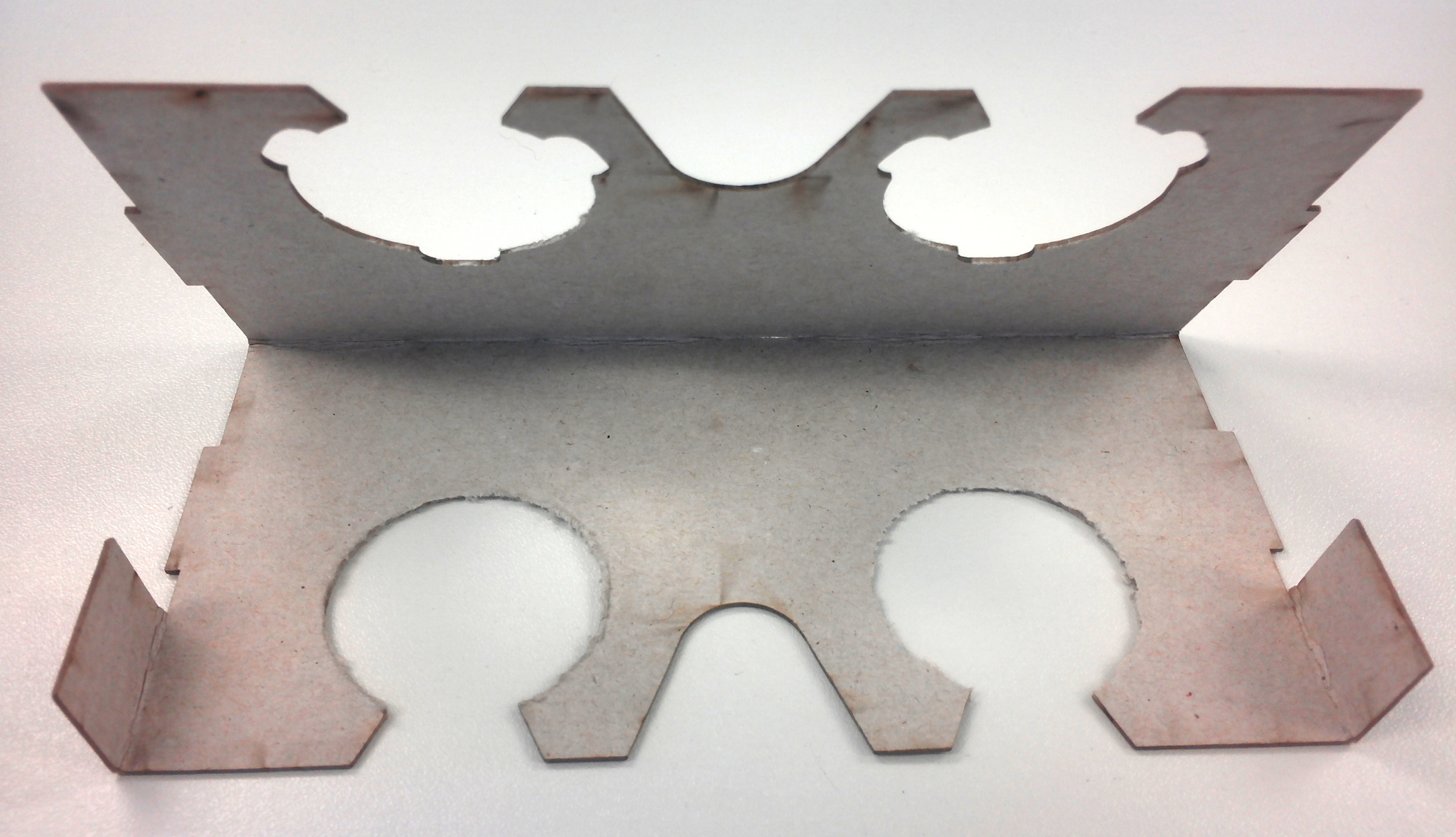
Figure 2: Creased edges piece A
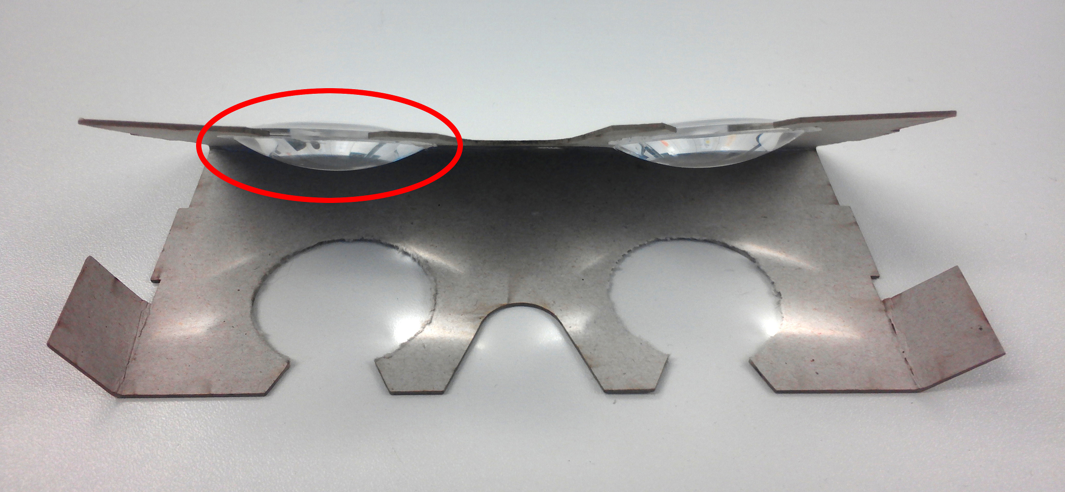
Figure 3: Insert the lenses
-
- Begin with part A. For this purpose, bend the provided edges of the part (see figure 2). Insert the lenses into the device (see figure 3), making sure that the larger curvature of the lenses is facing the other round aperture and press firmly. Glue the piece together (see figure 4). Finally, their part should look like in figure 5.
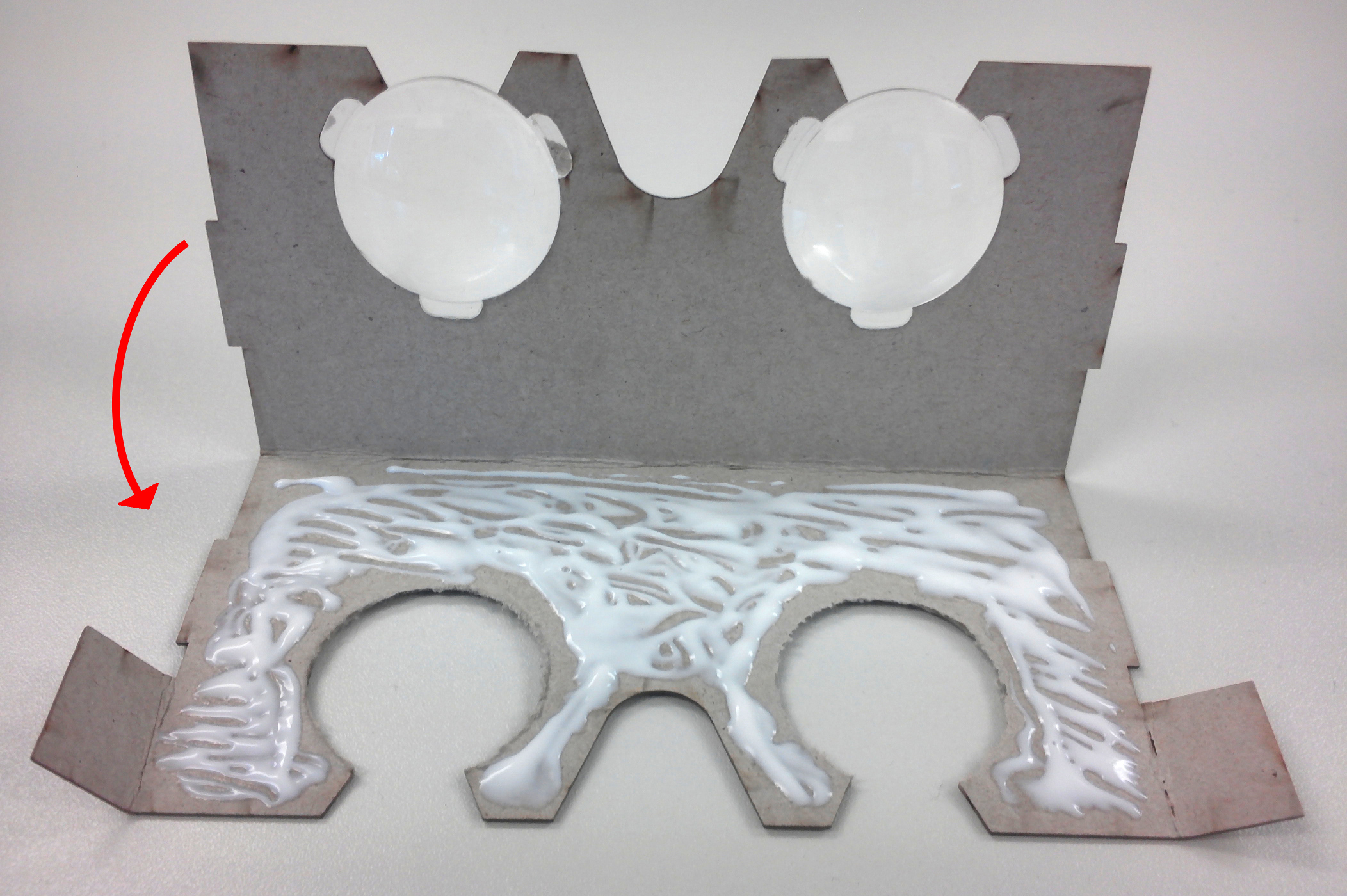
Figure 4: Glueing the piece A
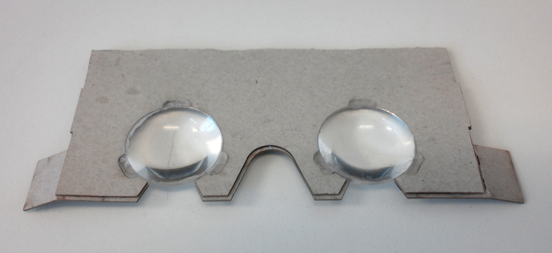
Figure 5: Final result piece A
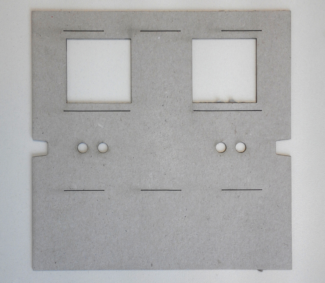
Figure 6: Piece B
-
- Continue with part B (see figure 6). In this step, you should also bend all the creased edges (Figure 7). Glue the connecting link to the other end of part B, creating a triangle like on figure (see figure 8).
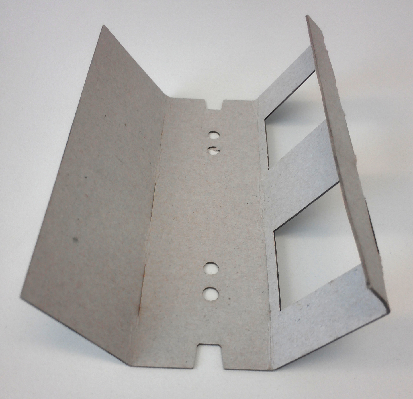
Figure 7: Creased edges of piece B
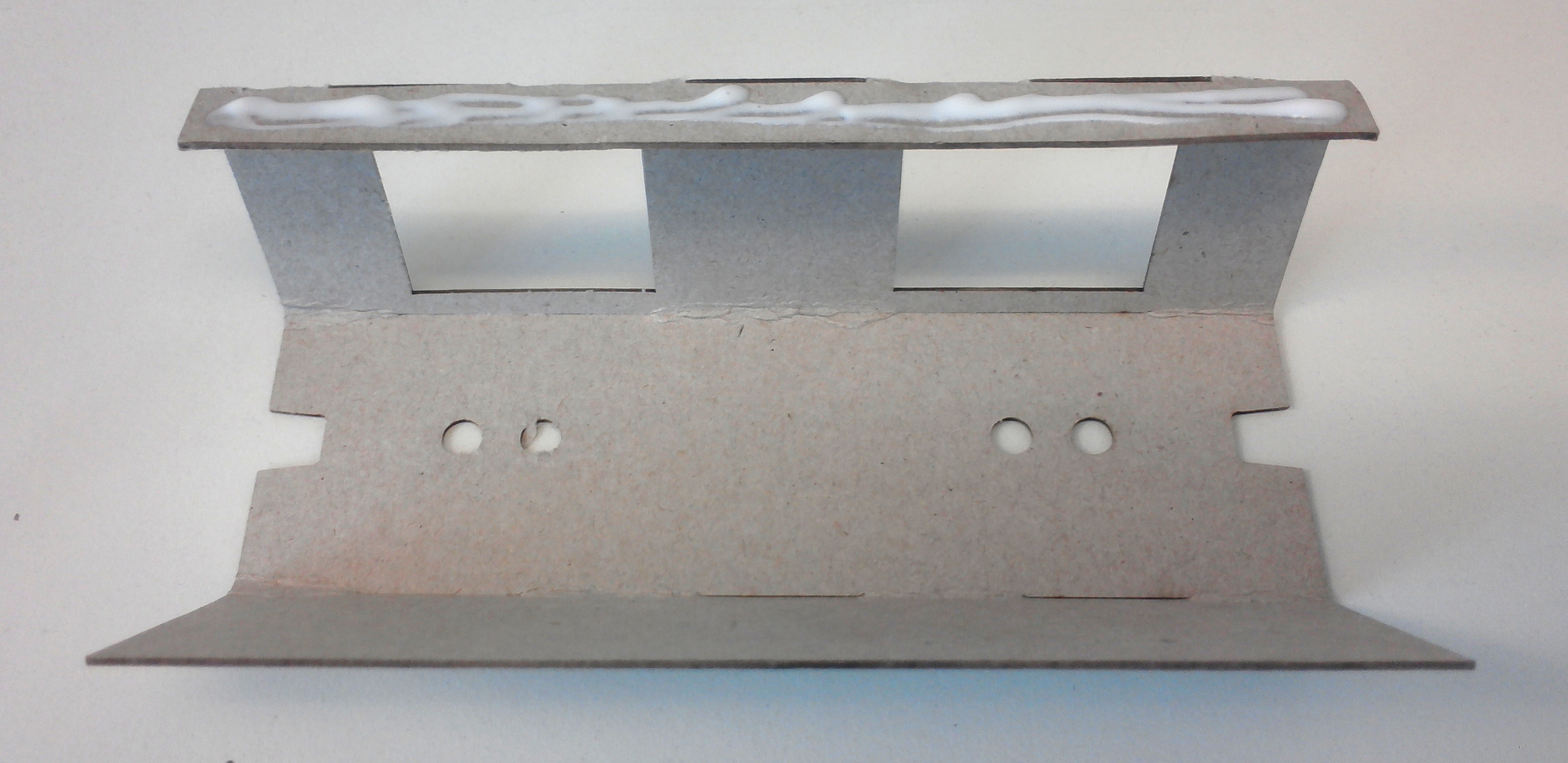
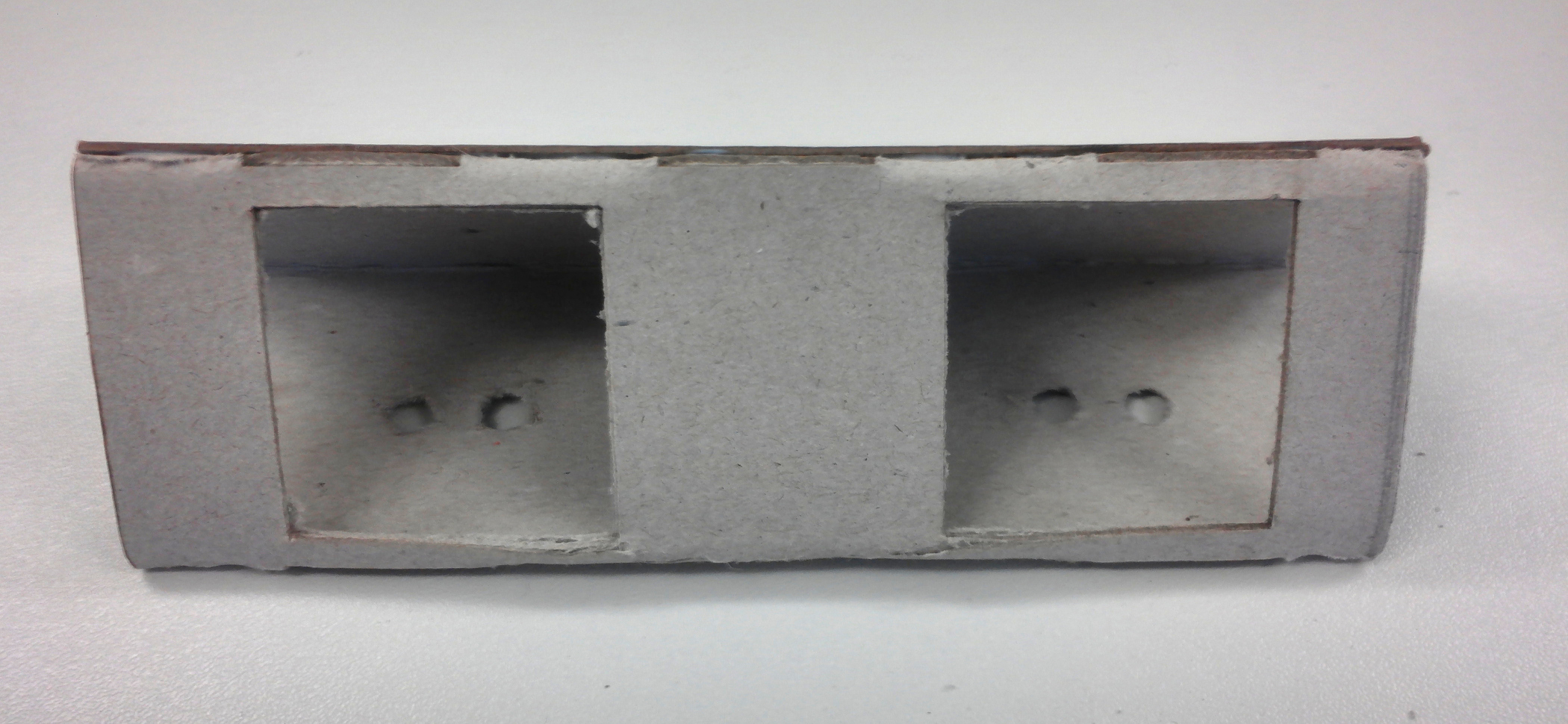
Figure 8: Glueing the connecting link to other end of the part B
-
- Fold the creased edges of part C (see figure 9). Make sure to fold the
edges to the inside of part C, an engraved “I” marks inside of part C (see figure 10). Place the previously finished part A on the slots in part C (see circle on figure 9 and figure 11). The auxiliary parts, which have been bent into part A, are now glued in the interior of part C (see figure 12). The final result is a combination of part A and part C.
- Fold the creased edges of part C (see figure 9). Make sure to fold the
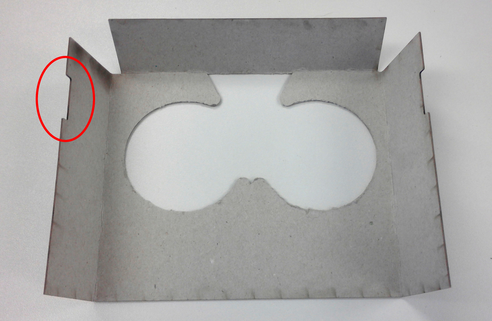
Figure 9: Part C and the slots for part A
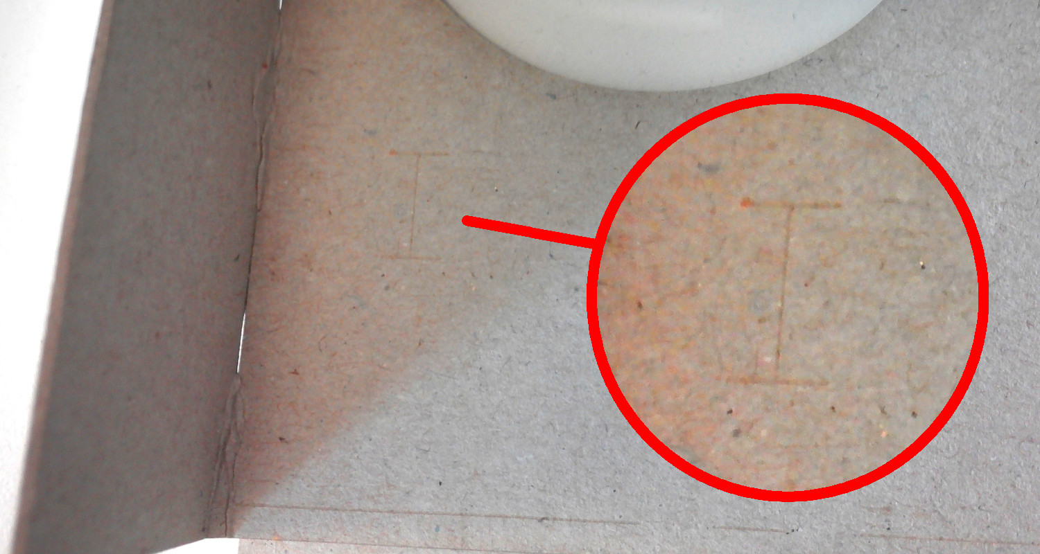
Figure 10: Part C and the slots for part A
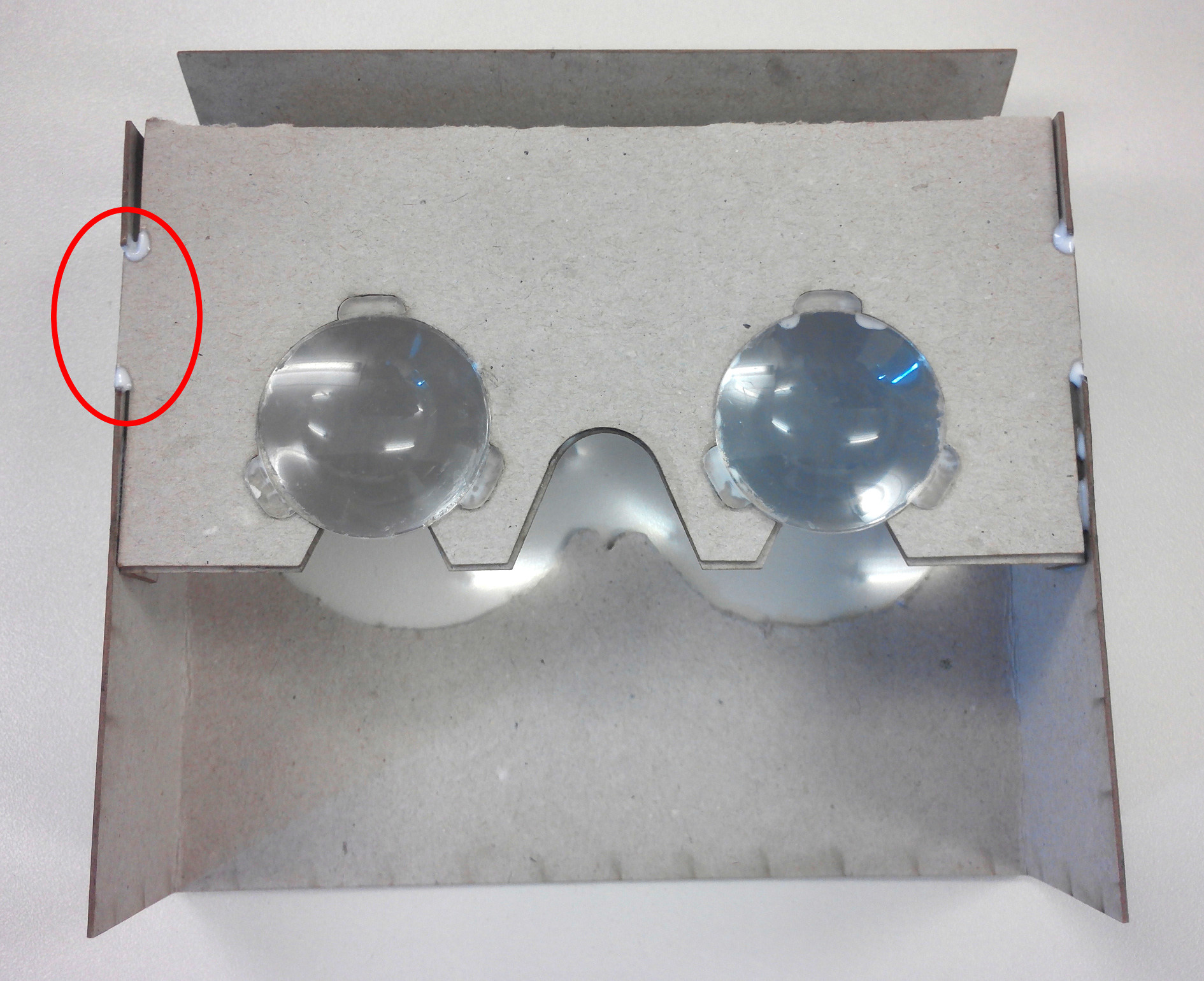
Figure 11: Part A in the slots of part C
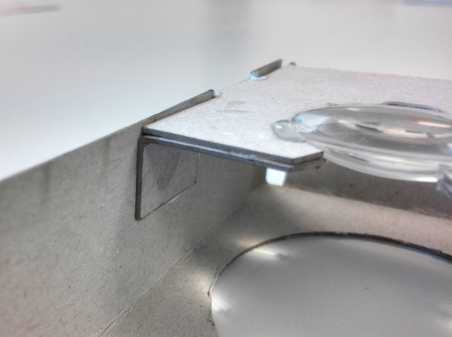
Figure 12: Attached the auxiliary pieces of part A to part C
-
- Now the result generated in step 4 is combined with part D (see figure 13). To do this, place the combination of A and C on the part D and glue them together. Then glue the top side of both parts together and place the side with the round aperture of part D on the side with the lenses of the A/C combination. The process is shown in figure 14.
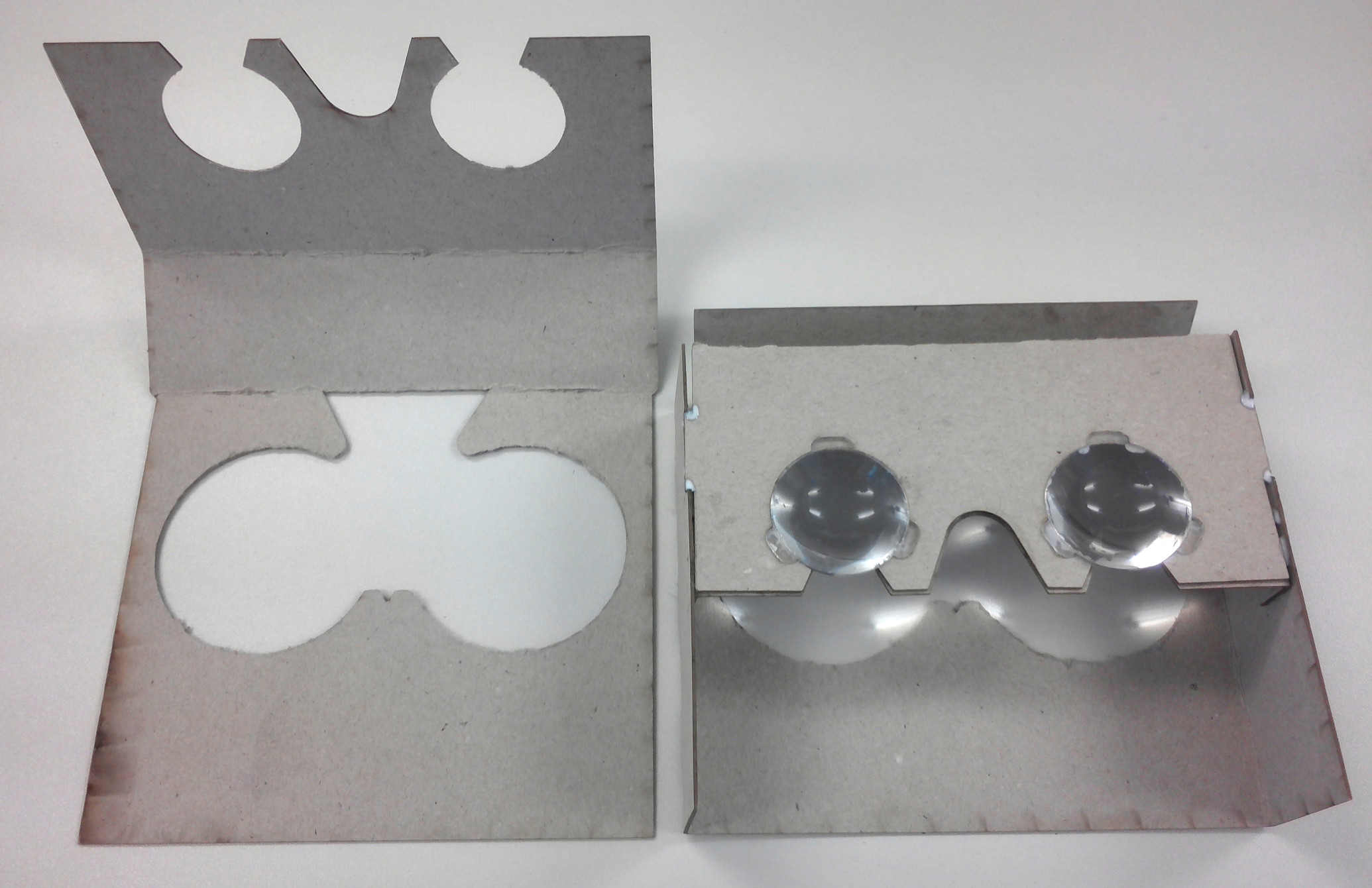
Figure 13: Left part D, right part A in combination with part C
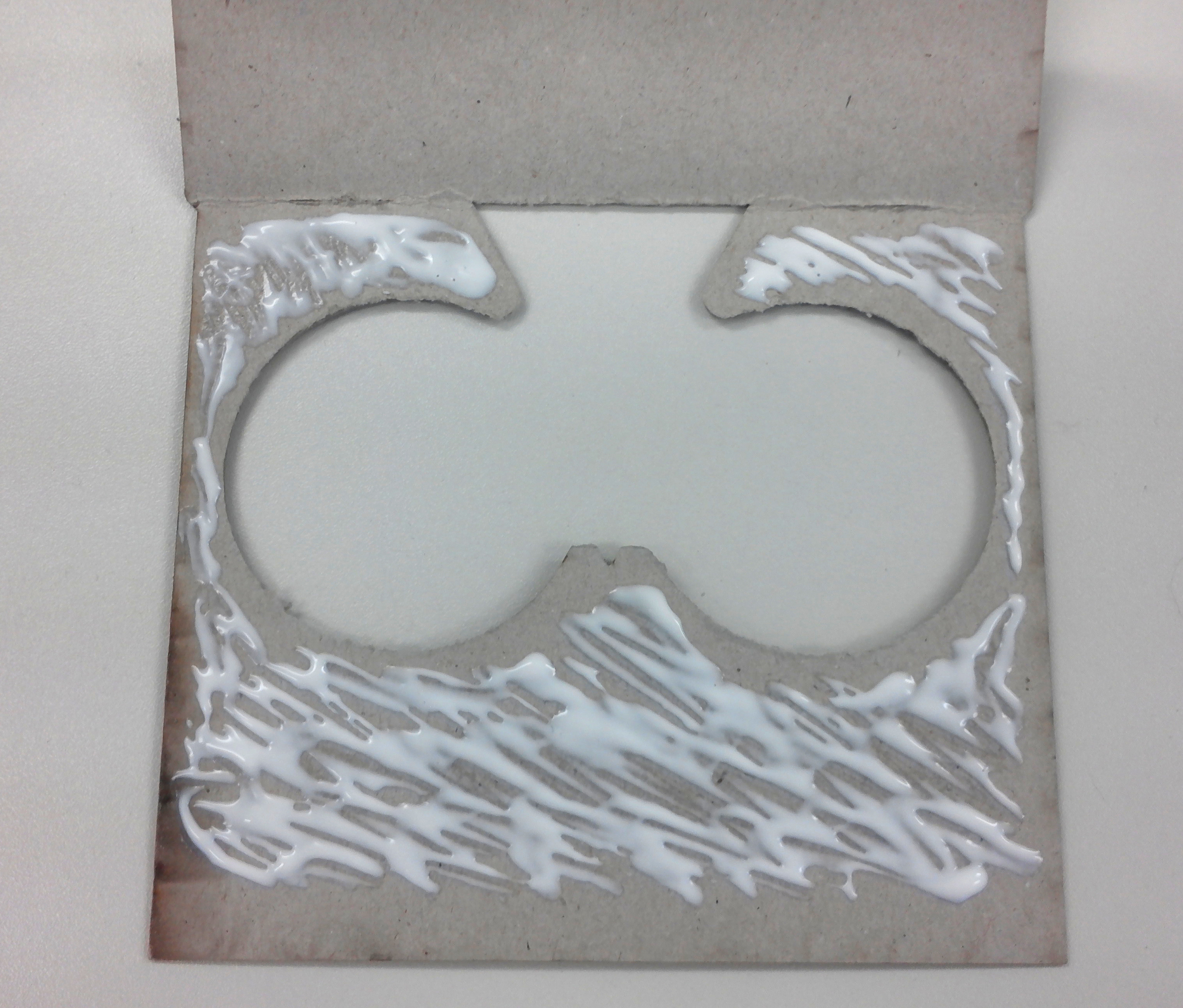
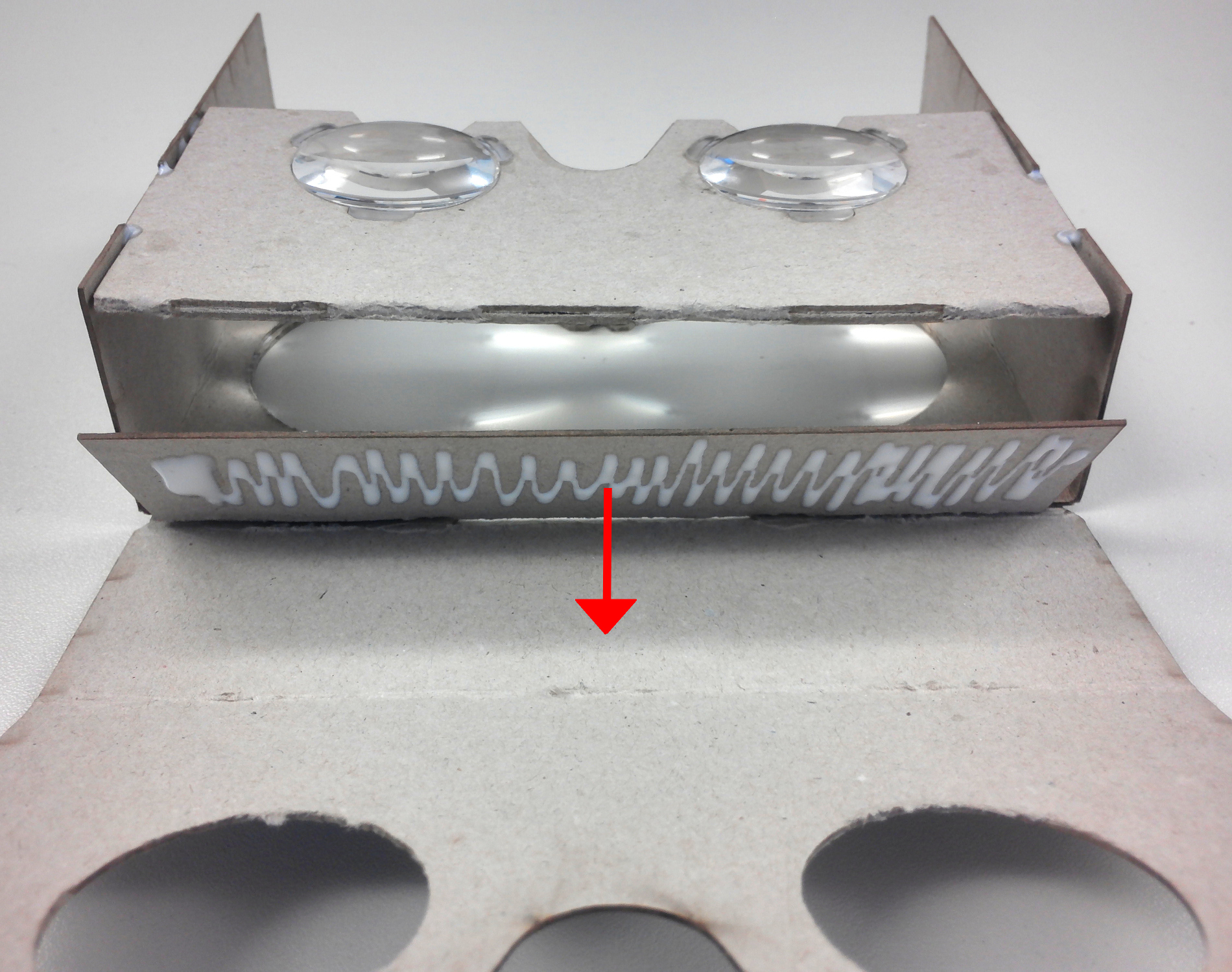
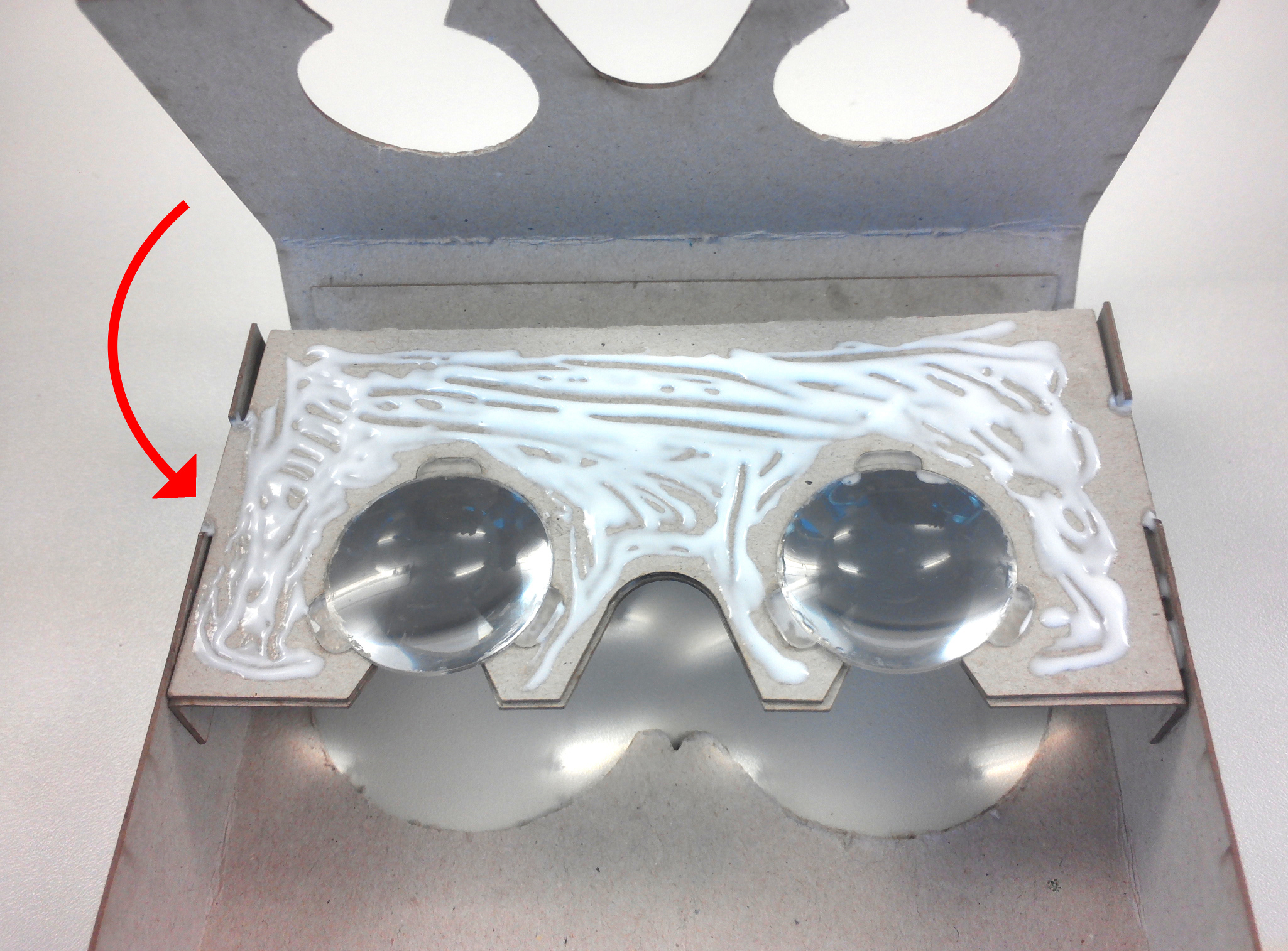
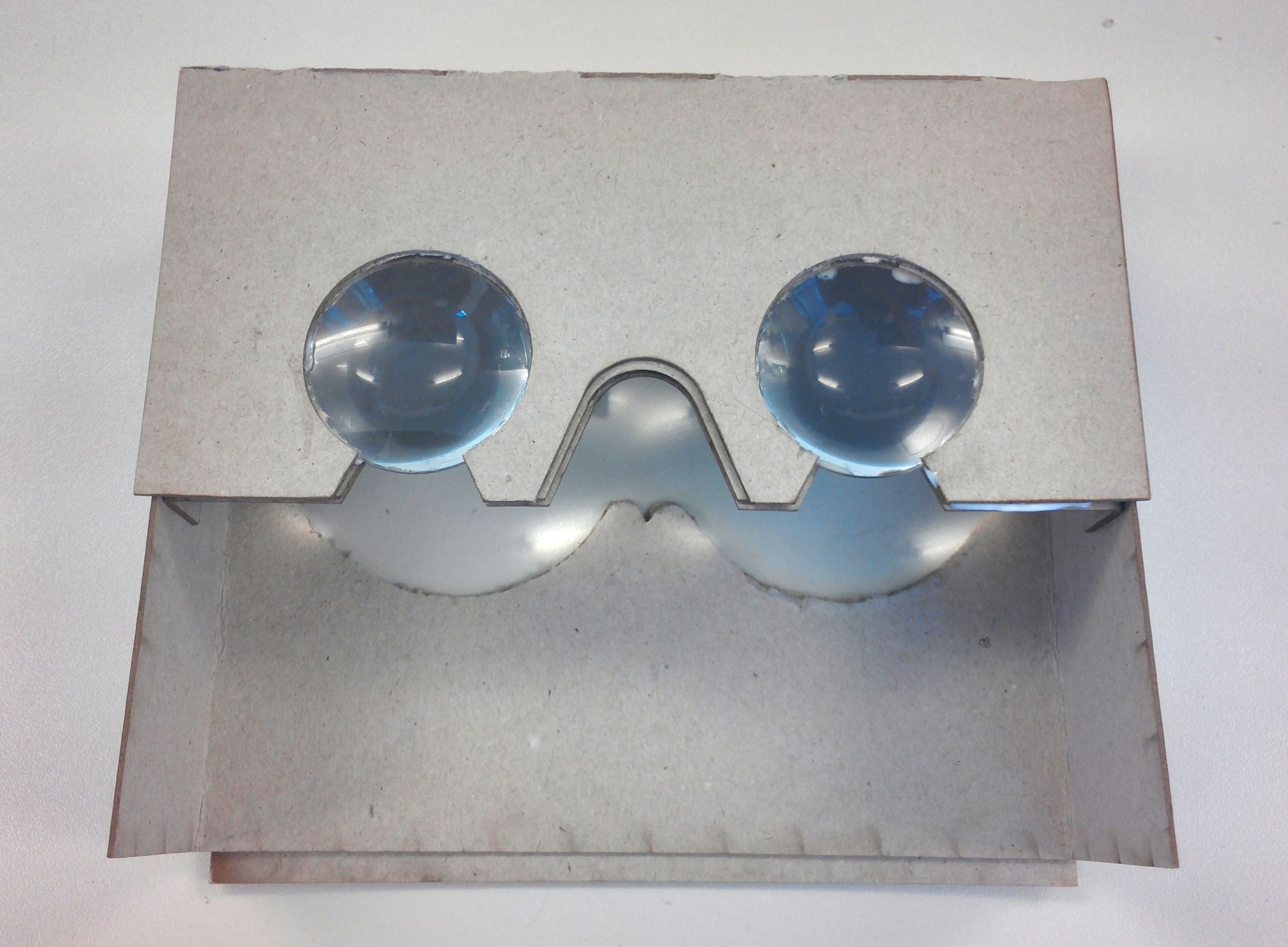
Figure 14: Positioning and Glueing of the A/C combination on part D
-
- Fold the edges of part E (see figure 15). Make sure to fold the edges to the bottom-side of part E, a “T” marks the top-side of part E. This is important because the hole for the smartphone camera must be on the correct side. Place the part created in the previous step on part E (bottom-side) and glue it (figure 16). Then glue the sides as well as the lid (Figures 16, 17 and 18).
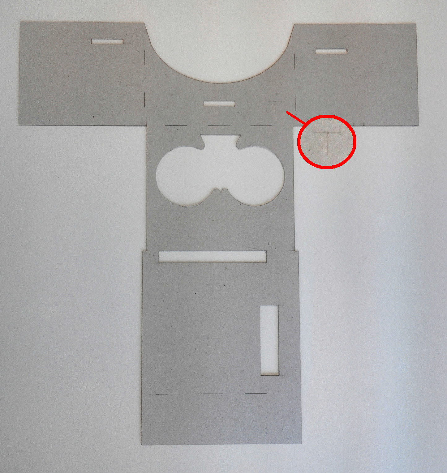
Figure 15: Part E

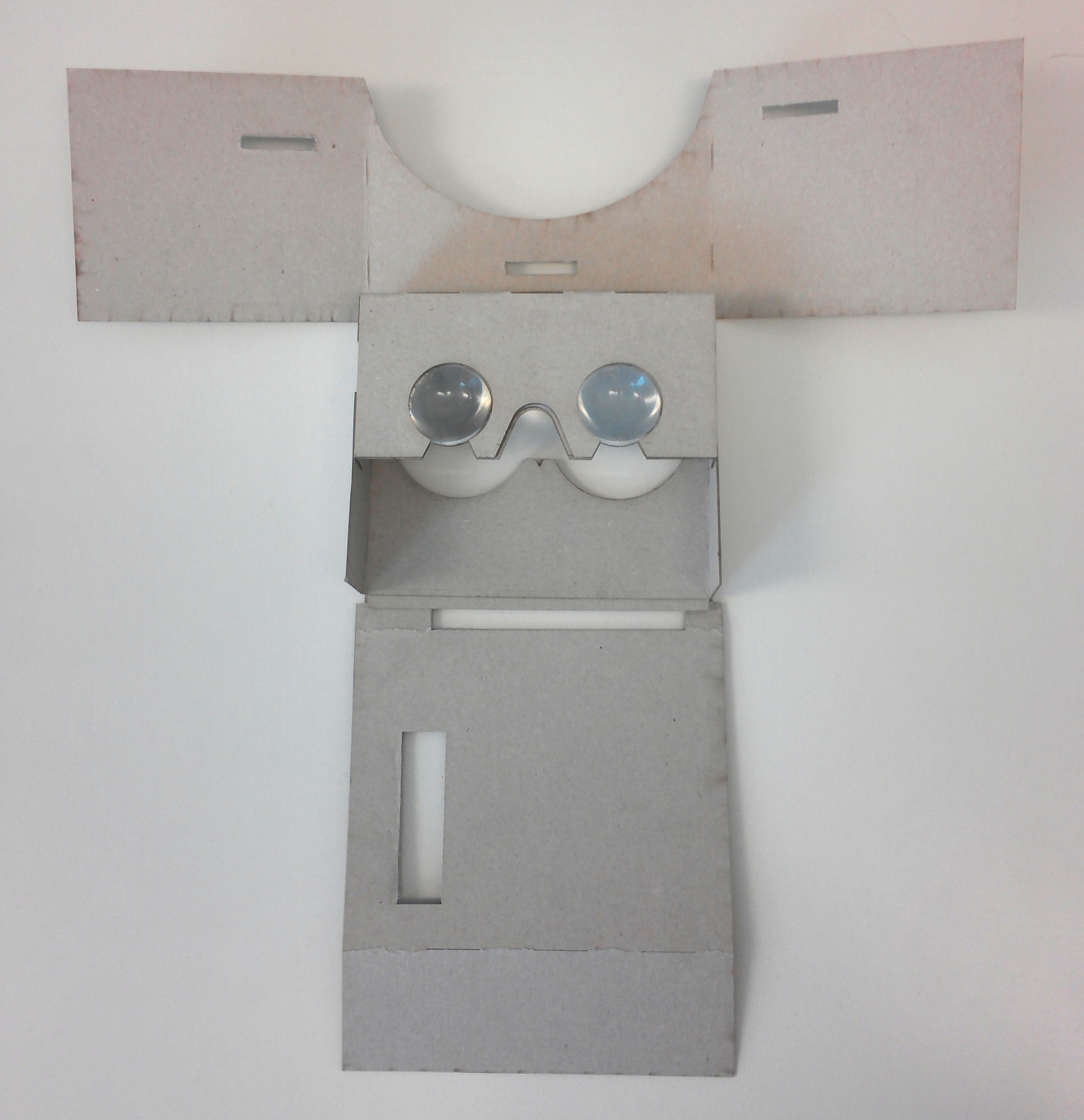
Figure 16: Combination of both parts
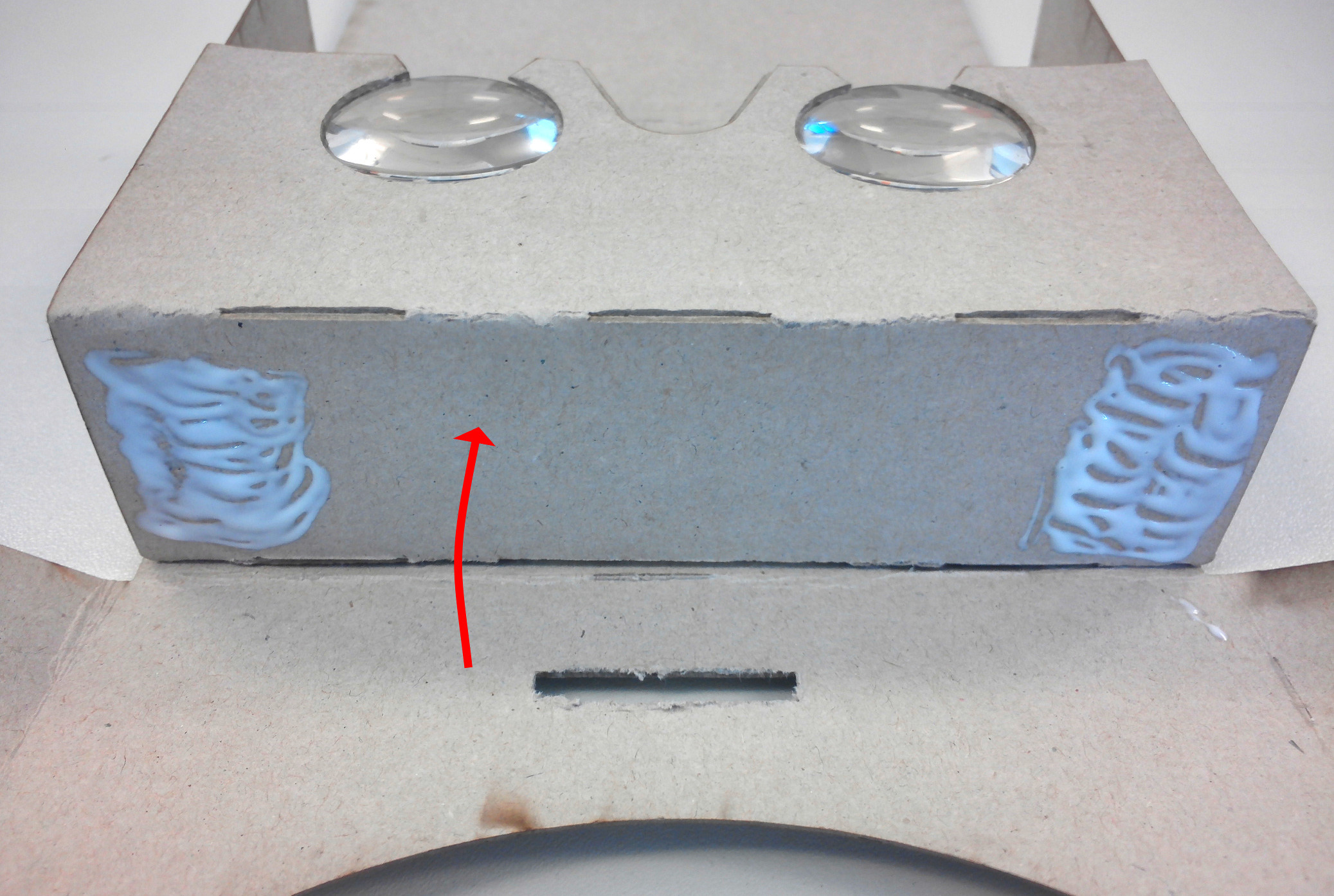
Figure 17: Glueing the top the cardboard
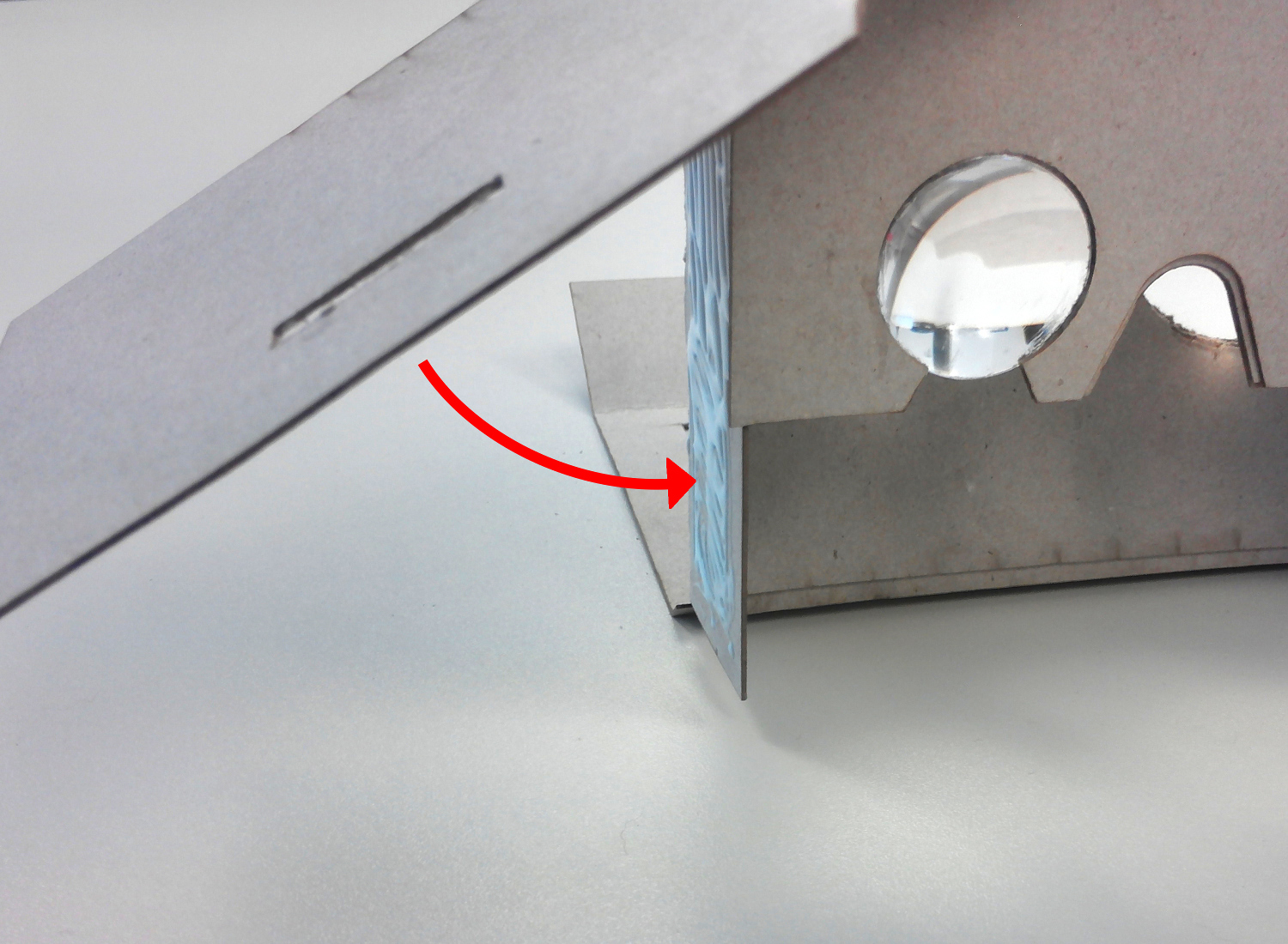
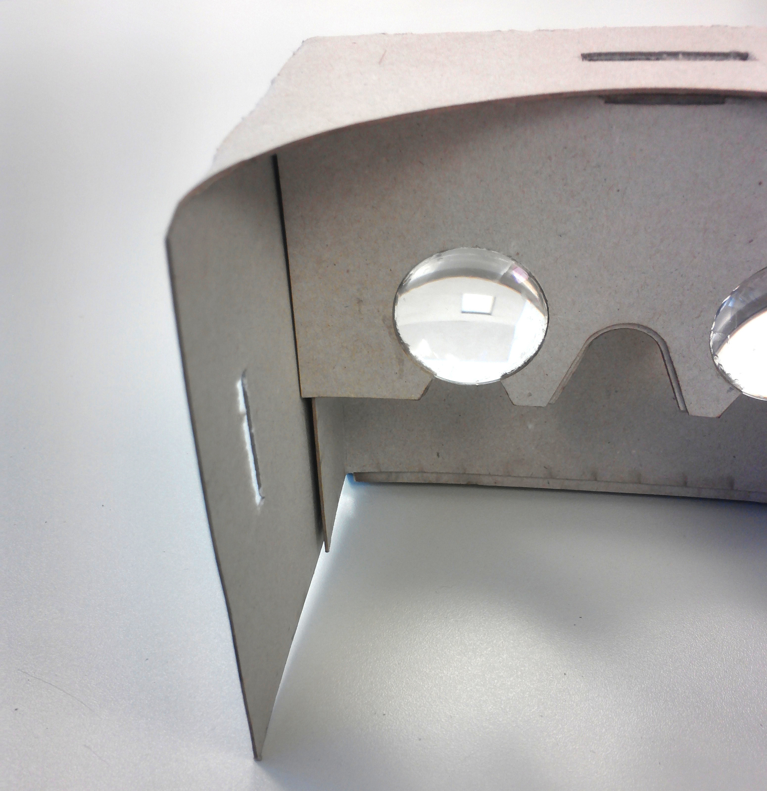
Figure 18: Positioning of the cardboard sides
-
- Glue the six equal parts of F on top of each other (Figure 19) and glue them between the engraved lines onto the cardboard (see figure 20).
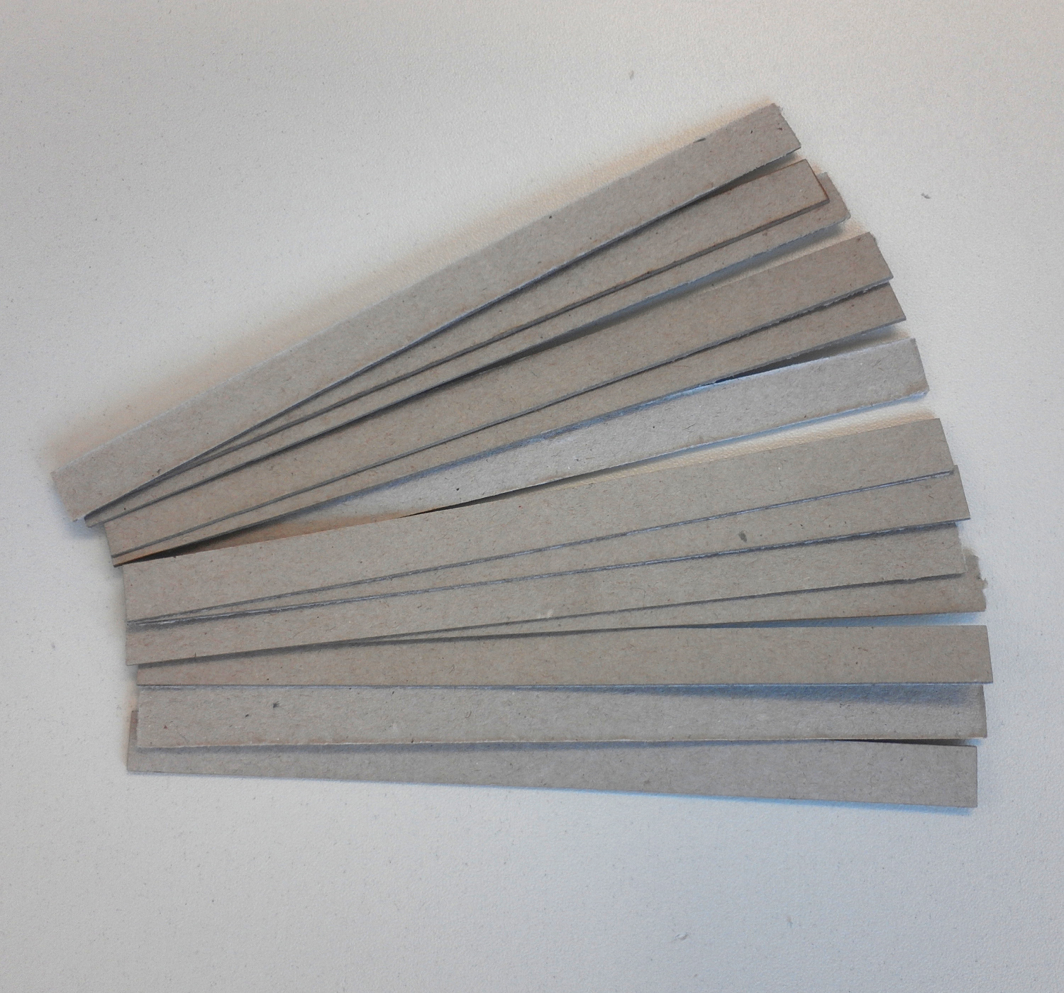
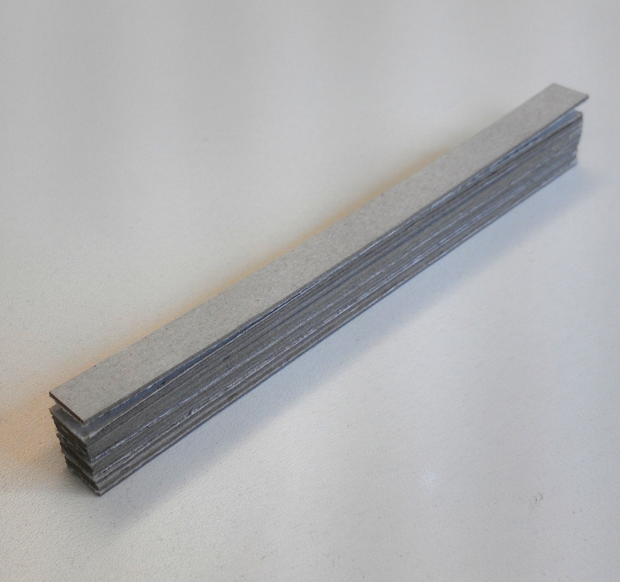
Figure 19: Assembling of part F
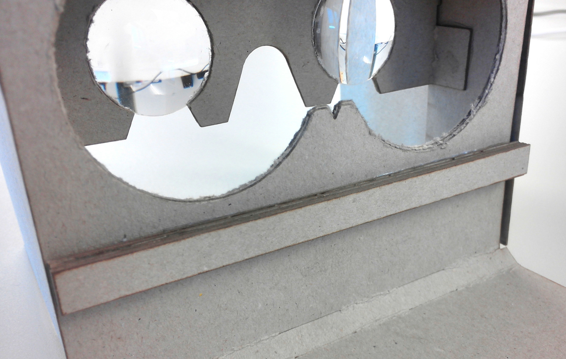
Figure 20: Positioning part F onto the cardboard
-
- For the next step take some foam rubber and cut out a stripe and a triangle, like the ones shown in figure 21. Then glue them to the inside of the cardboard: Attach the stripe into the gap between the lenses and the triangle on the area above it. The result should look like on figure 22.
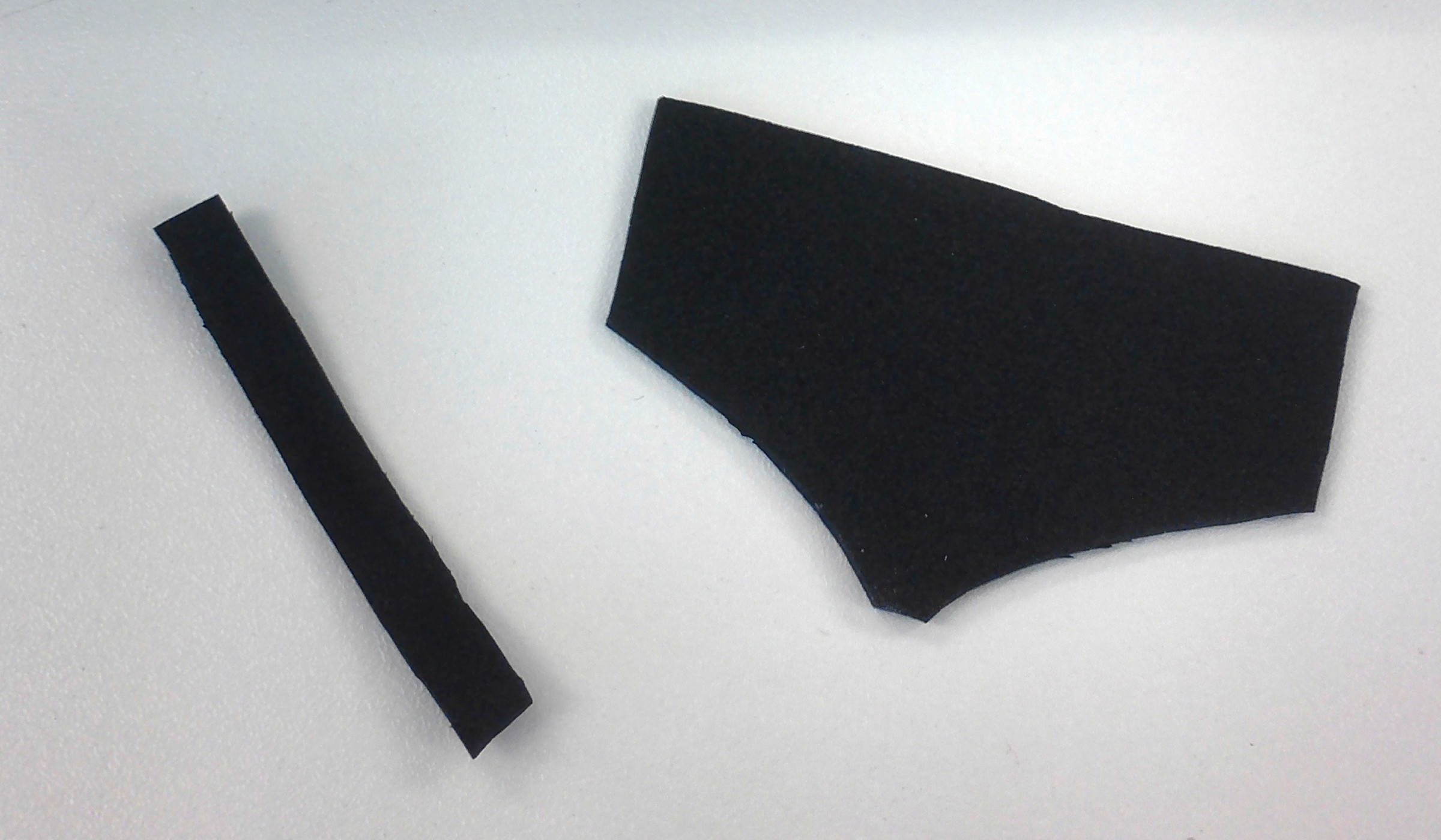
Figure 21: cut foam rubber as padding for the inside of the cardboard
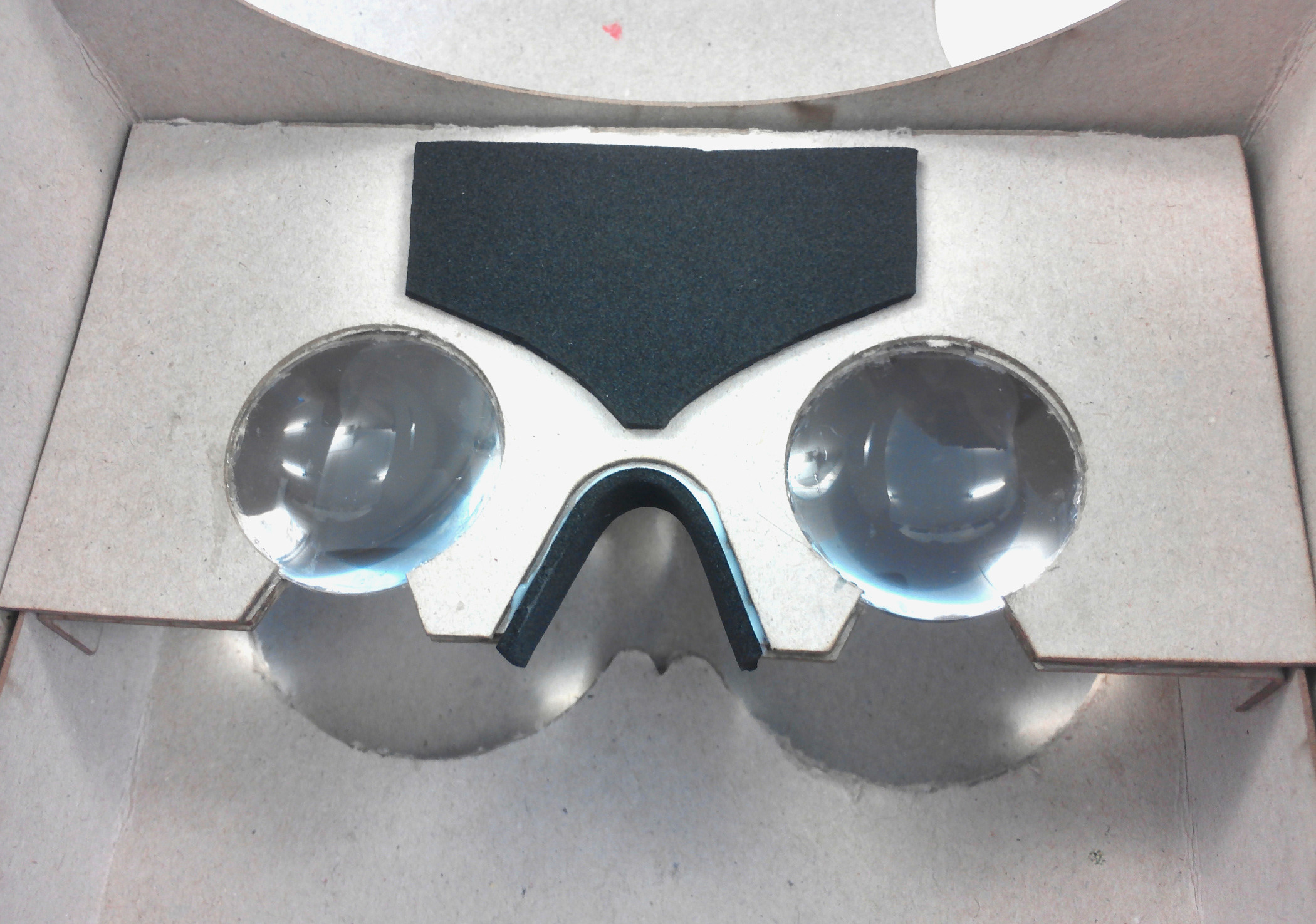
Figure 22: foam rubber attached on the cardboard
- For the next step take some foam rubber and cut out a stripe and a triangle, like the ones shown in figure 21. Then glue them to the inside of the cardboard: Attach the stripe into the gap between the lenses and the triangle on the area above it. The result should look like on figure 22.
-
- Next, take some more foam rubber and cut out a rectangle (see figure 23). Glue this rectangle between the squarish apertures of part B as shown in figure 24.
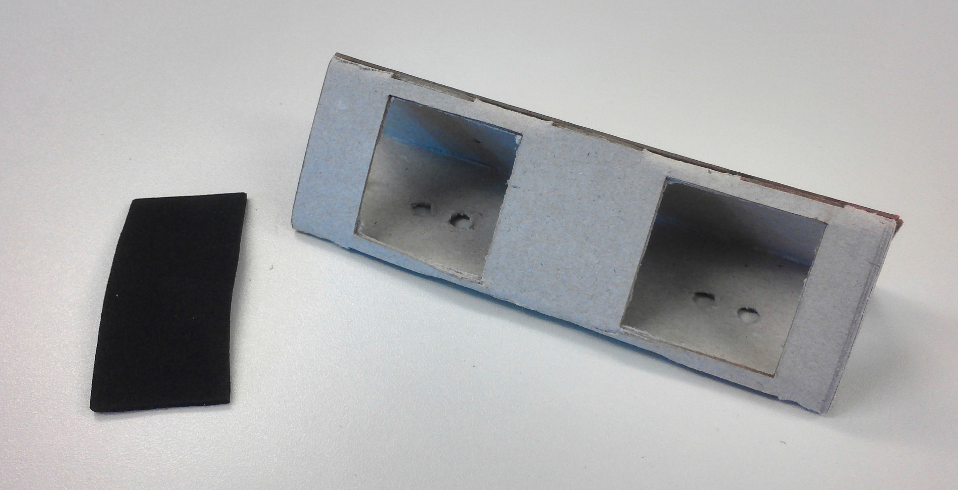
Figure 23: cut foam rubber as padding for the inside of the cardboard
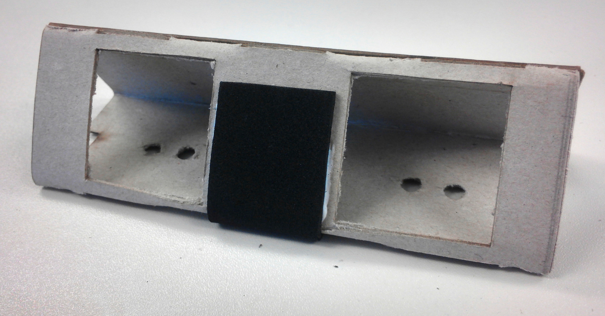
Figure 24: foam rubber attached on the cardboard
- Next, take some more foam rubber and cut out a rectangle (see figure 23). Glue this rectangle between the squarish apertures of part B as shown in figure 24.
-
- Now, take part B ,the camera, a cord stopper and two thin rubber bands (see figure 25) to attach the camera to part B. To do this, pull through the corner holes of the camera two thin rubber bands and pull them at the back of part B through the provided holes and secure the bands with a cord stopper (see figure 26).
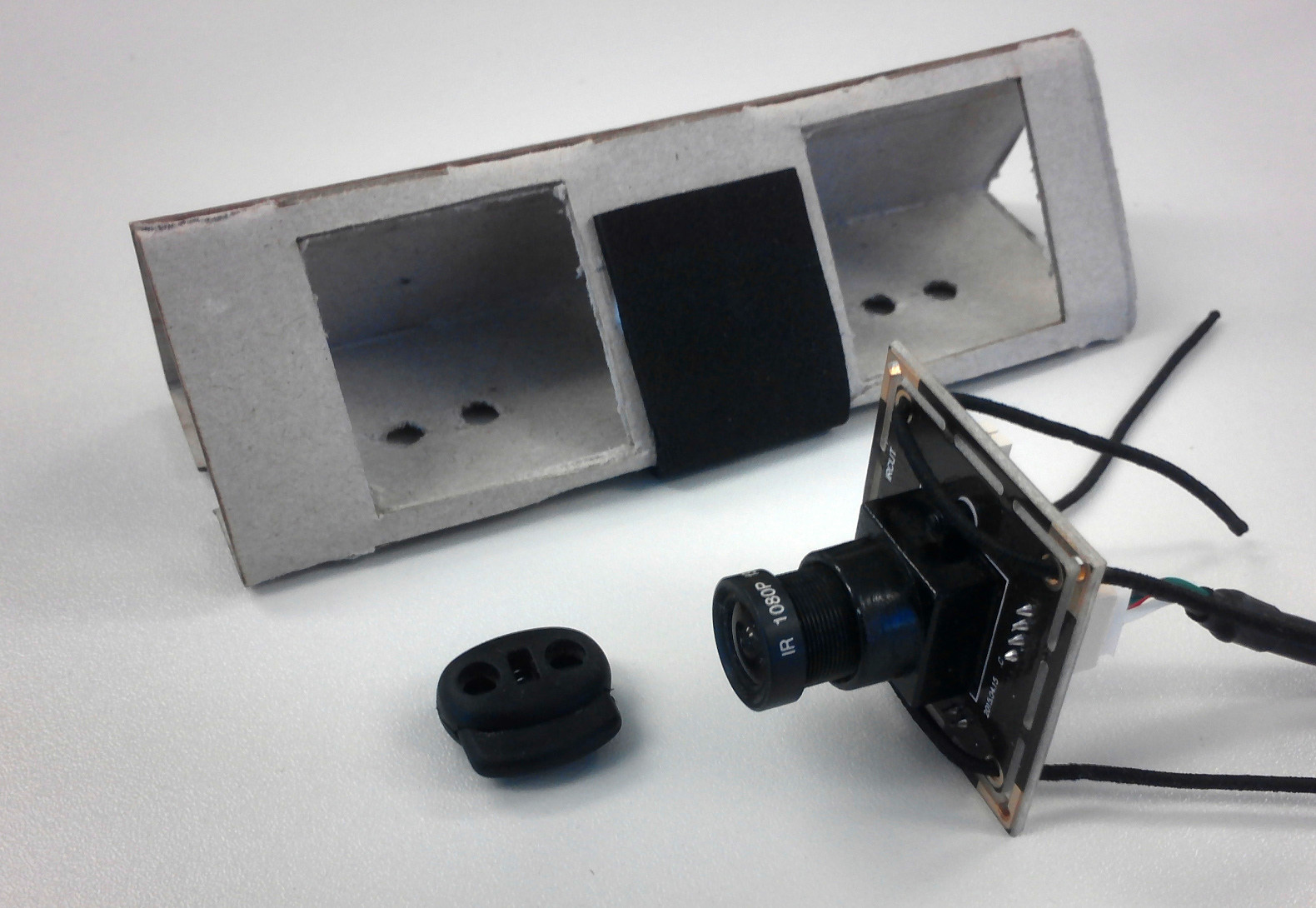
Figure 25: Camera attached on part B
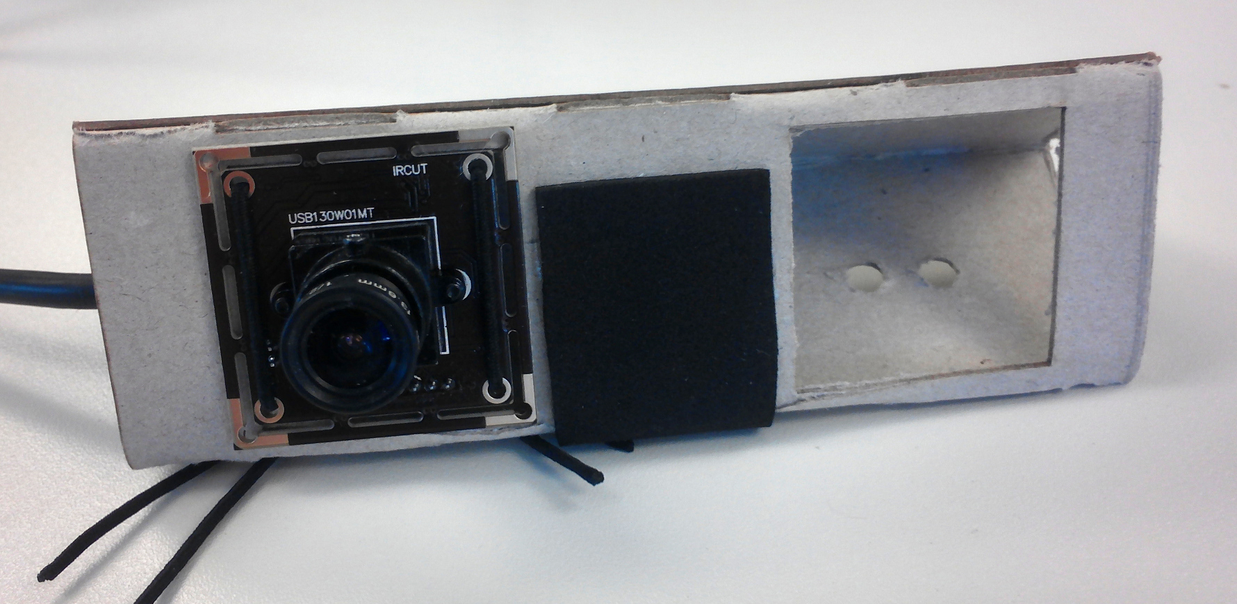
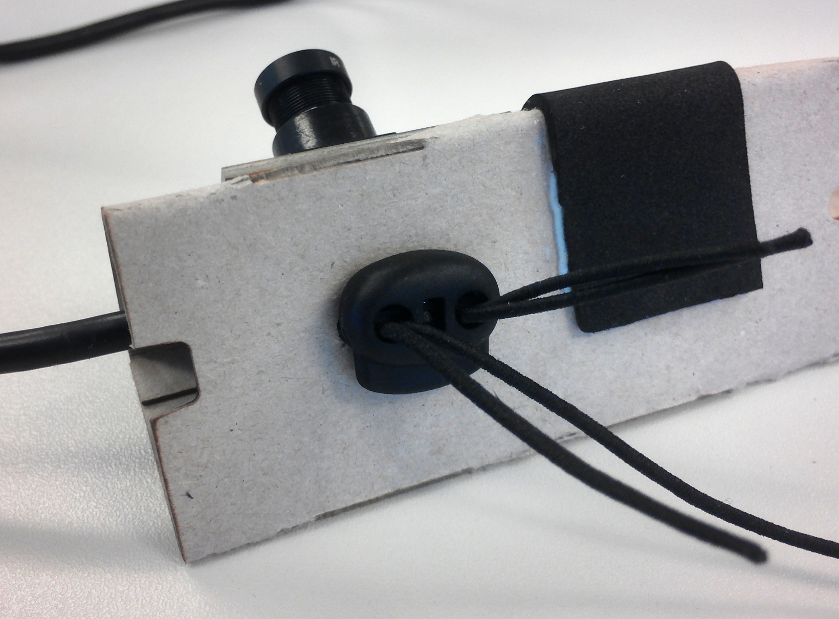
Figure 26: Camera attached on part B
- Now, take part B ,the camera, a cord stopper and two thin rubber bands (see figure 25) to attach the camera to part B. To do this, pull through the corner holes of the camera two thin rubber bands and pull them at the back of part B through the provided holes and secure the bands with a cord stopper (see figure 26).
-
- Now take the camera and a screwdriver. In this step you have to adjust the focus of the camera for the short distance. This is necessary because the camera image of the eye need to be sharp for easier pupil detection in Pupil Capture. The focus of the camera we used, the ELP 960P HD 1.3 MP, can be set by release the screw on the objective and turn the objective with the clockwise direction till the focal point is at a distance of 25 to 30mm. Figure 27 visualize this process and figure 28 shows the camera image before (left) and after (right) setting the focal point.
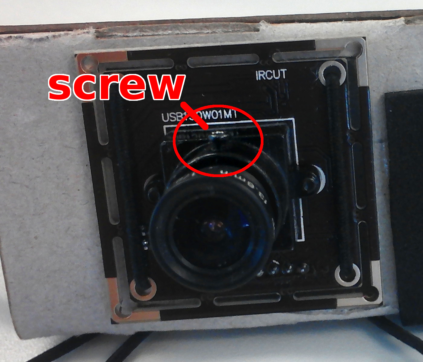
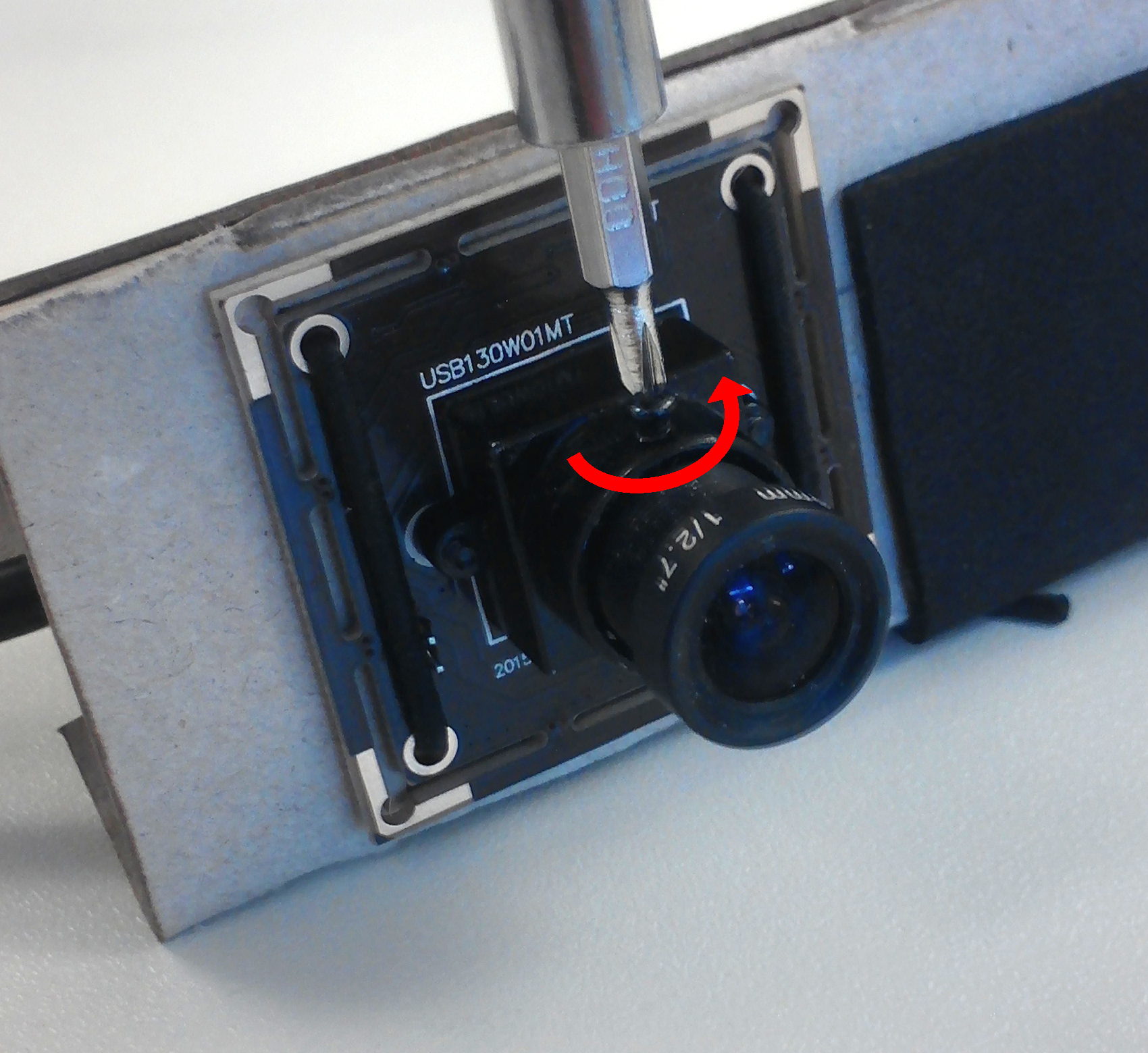
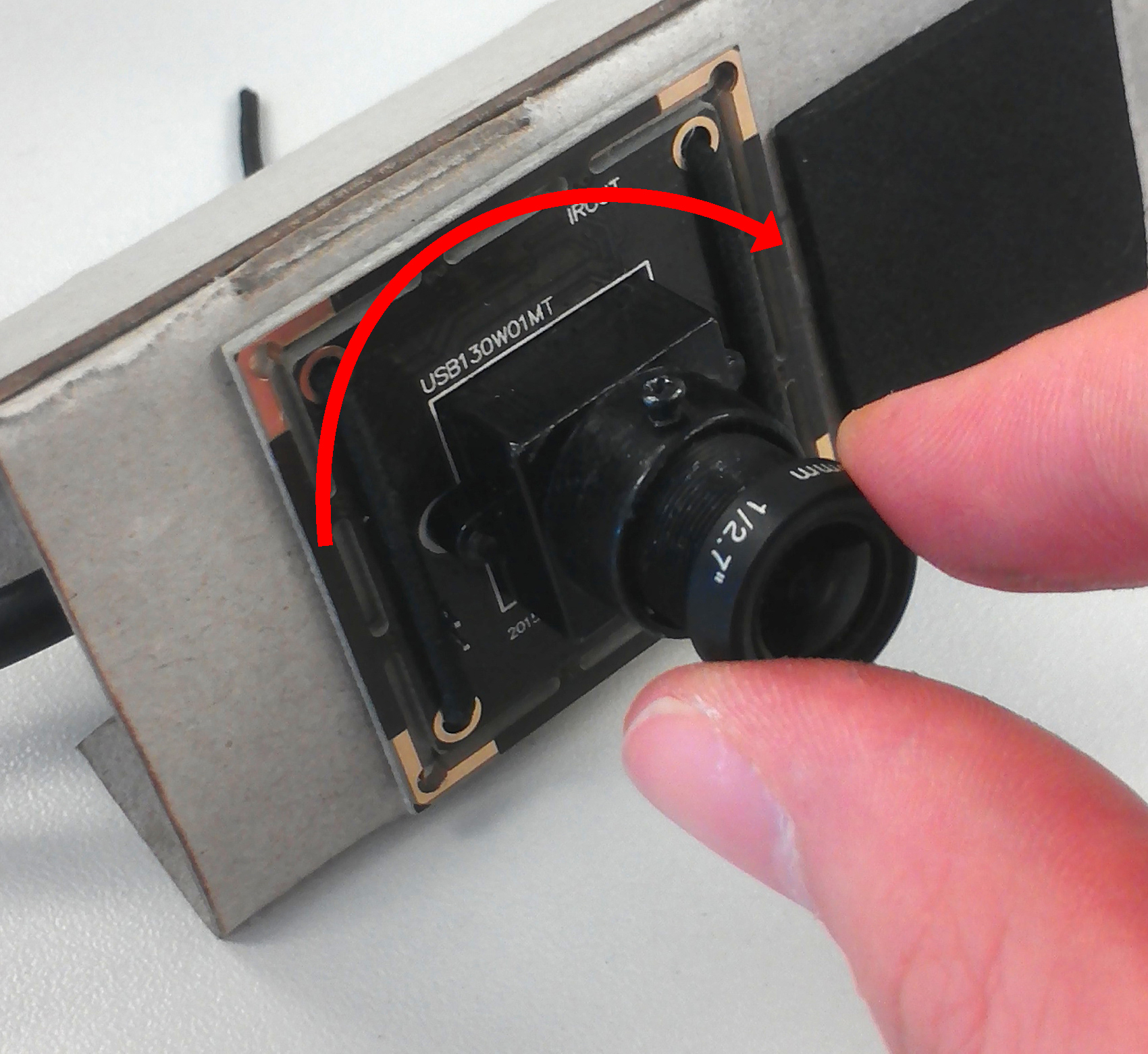
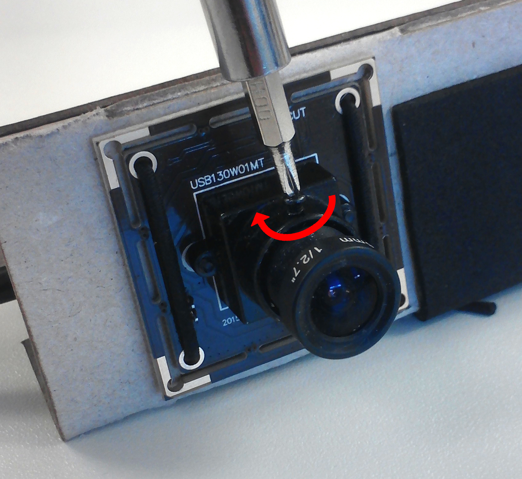
Figure 27: Setting the focal point on an ELP 960P HD 1.3 MP
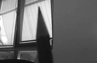
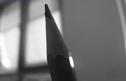
Figure 28: Camera image before (left) and after (right) setting the focal point
correctly
- Now take the camera and a screwdriver. In this step you have to adjust the focus of the camera for the short distance. This is necessary because the camera image of the eye need to be sharp for easier pupil detection in Pupil Capture. The focus of the camera we used, the ELP 960P HD 1.3 MP, can be set by release the screw on the objective and turn the objective with the clockwise direction till the focal point is at a distance of 25 to 30mm. Figure 27 visualize this process and figure 28 shows the camera image before (left) and after (right) setting the focal point.
-
- The next step is to place the circuit board on the camera (see figure 29). It’s recommended to place some hot glue on the bottom-side of the circuit board to prevent short circuit. Then attach the circuit board on the camera. To do this rotate the circuit board 45 degrees to pull it over the screw of the camera and then rotate it back like in figure 30.
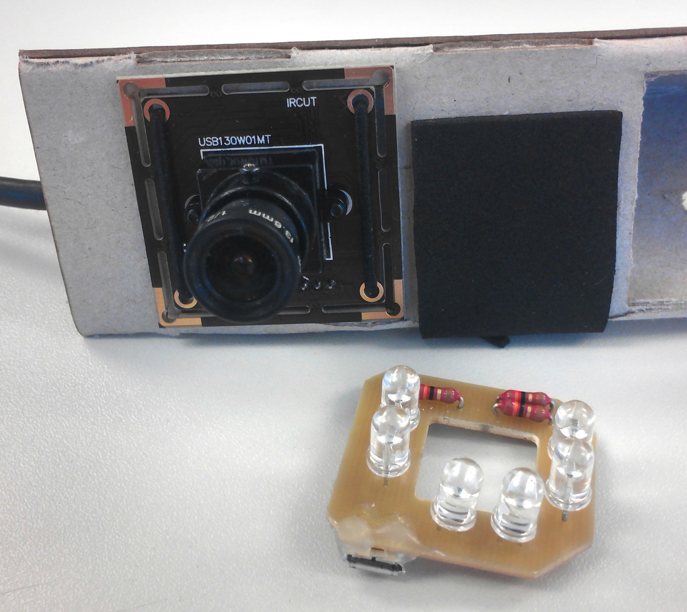
Figure 29: Circuit board and the camera
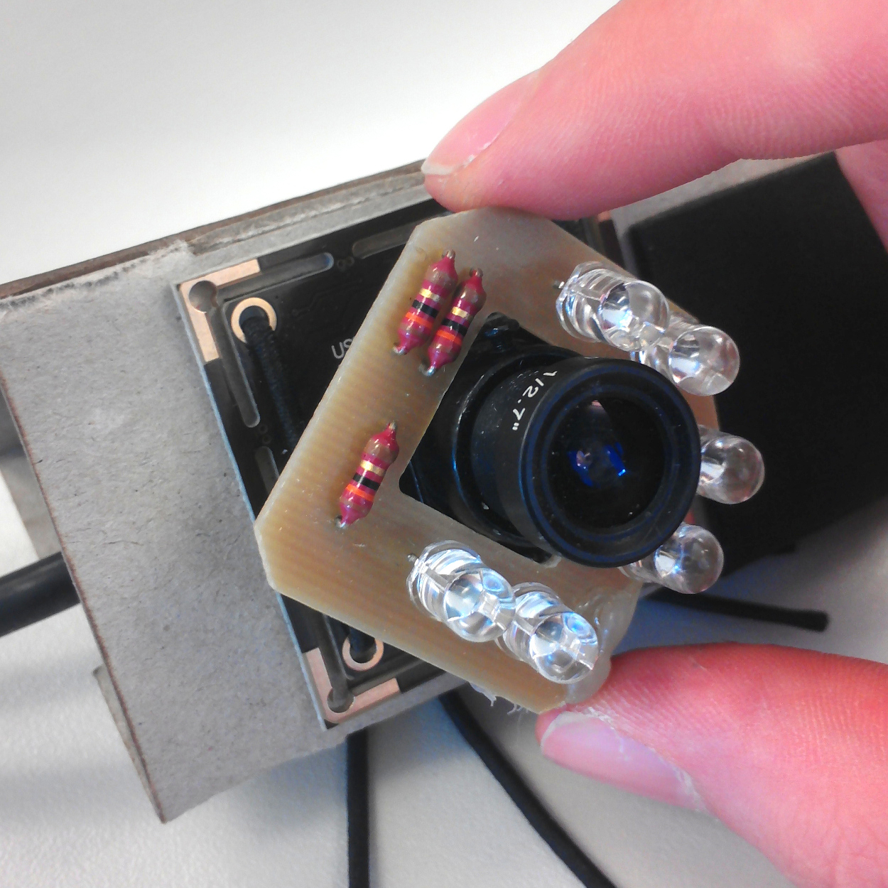
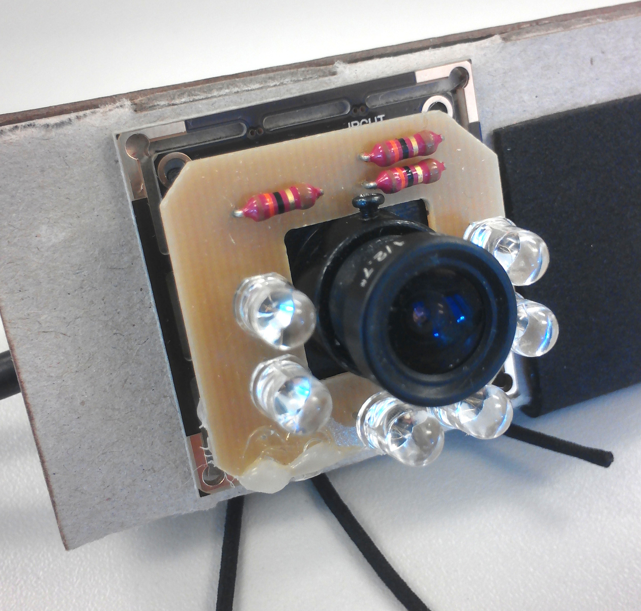
Figure 30: Attaching the circuit board on the camera
- The next step is to place the circuit board on the camera (see figure 29). It’s recommended to place some hot glue on the bottom-side of the circuit board to prevent short circuit. Then attach the circuit board on the camera. To do this rotate the circuit board 45 degrees to pull it over the screw of the camera and then rotate it back like in figure 30.
-
- Finally, glue the part B with hot glue into the cardboard. The bottom edge of part B should fit the marked line inside the cardboard. The camera objective should be centered under the lens, like shown in figure 31. The result should look like on figure 32.
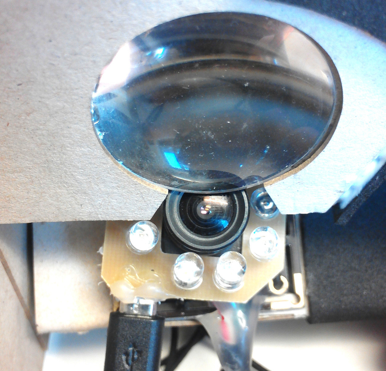
Figure 31: Objective of the camera is centered under the lens
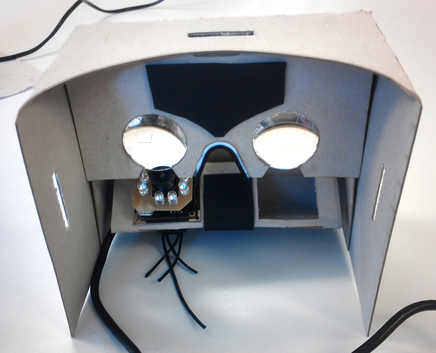
Figure 32: Cardboard with camera and board as well as the attachment
- Finally, glue the part B with hot glue into the cardboard. The bottom edge of part B should fit the marked line inside the cardboard. The camera objective should be centered under the lens, like shown in figure 31. The result should look like on figure 32.
-
- For the next step, take the Velcro rubber bands and two male Velcro tapes (see figure 33). Sew on each end of the female Velcro rubber bands a male Velcro tape.
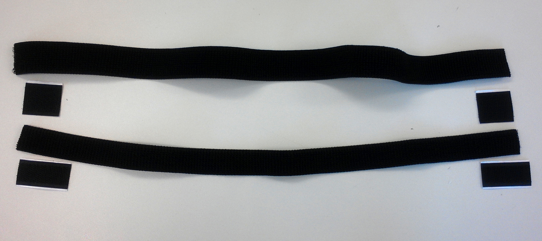
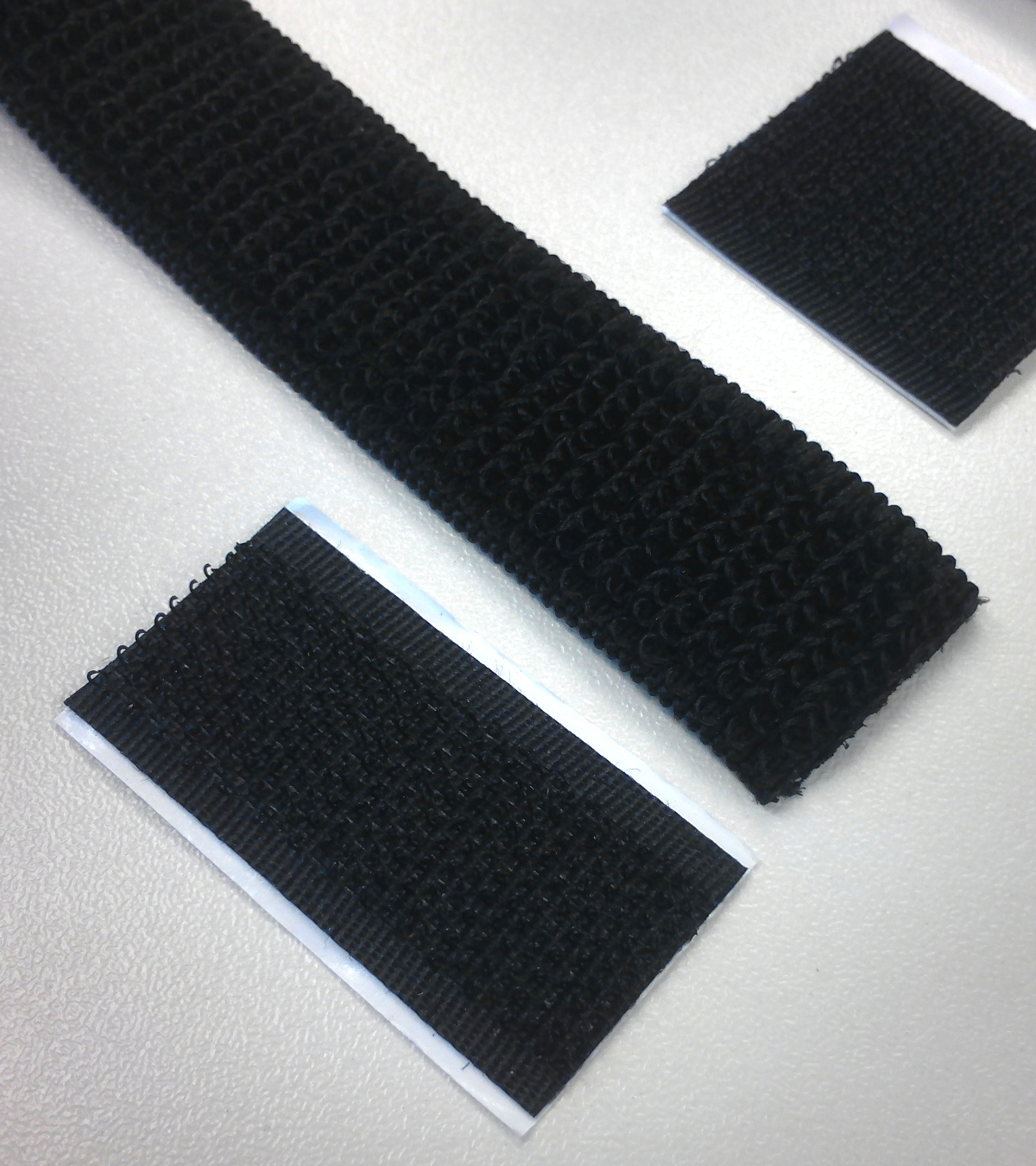
Figure 33: Female Velcro rubber bands and male Velcro tapes
- For the next step, take the Velcro rubber bands and two male Velcro tapes (see figure 33). Sew on each end of the female Velcro rubber bands a male Velcro tape.
-
- Now take one Velcro rubber band attach one end to the left slot of the cardboard, as shown in figure 34. Then pull the other end of the Velcrorubber band though the right slot of the cardbard, as shown in figure 35. The result should looks like on the figure 36.
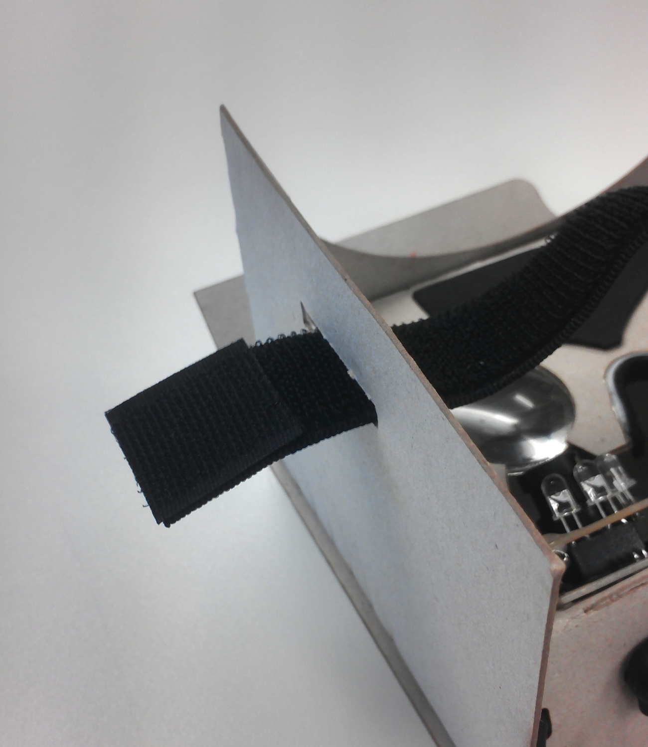
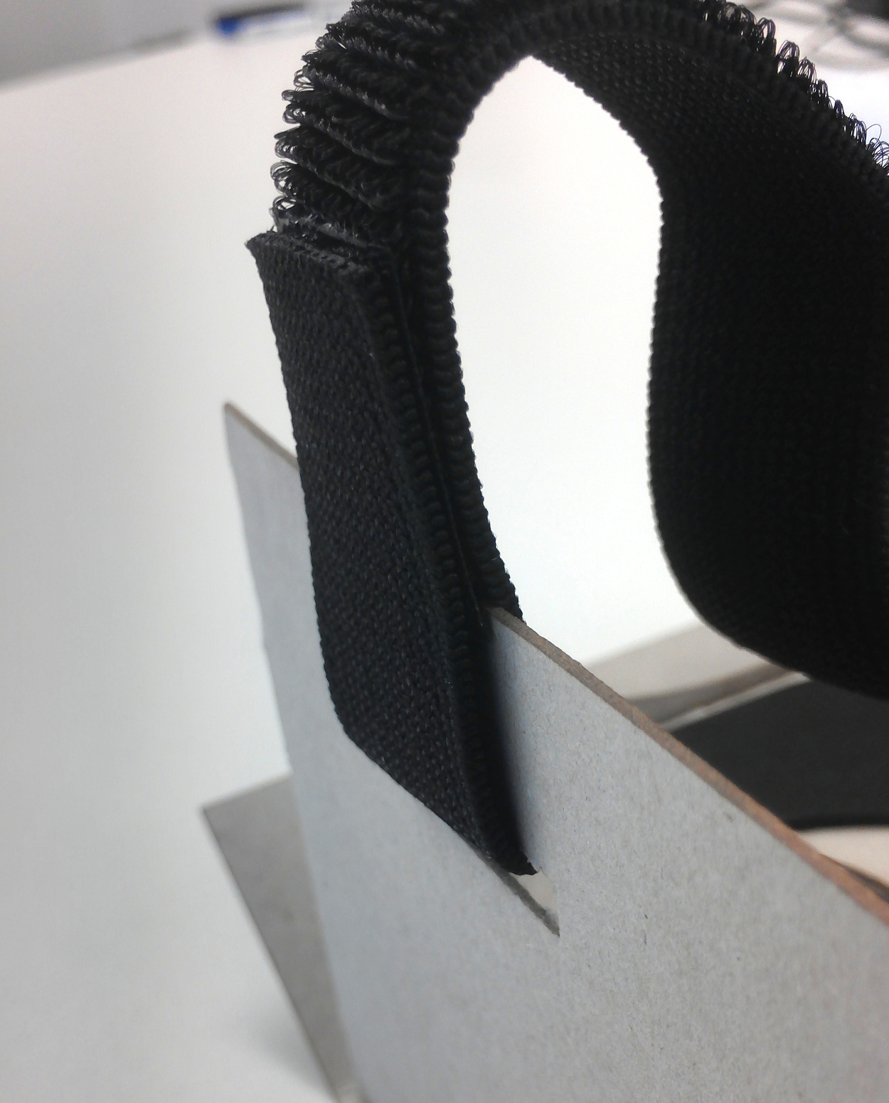
Figure 34: Attach the rubber band on the left side of the cardboard
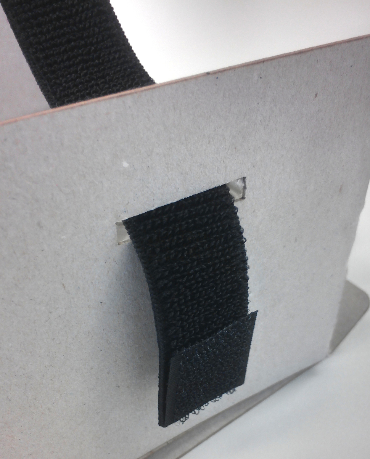
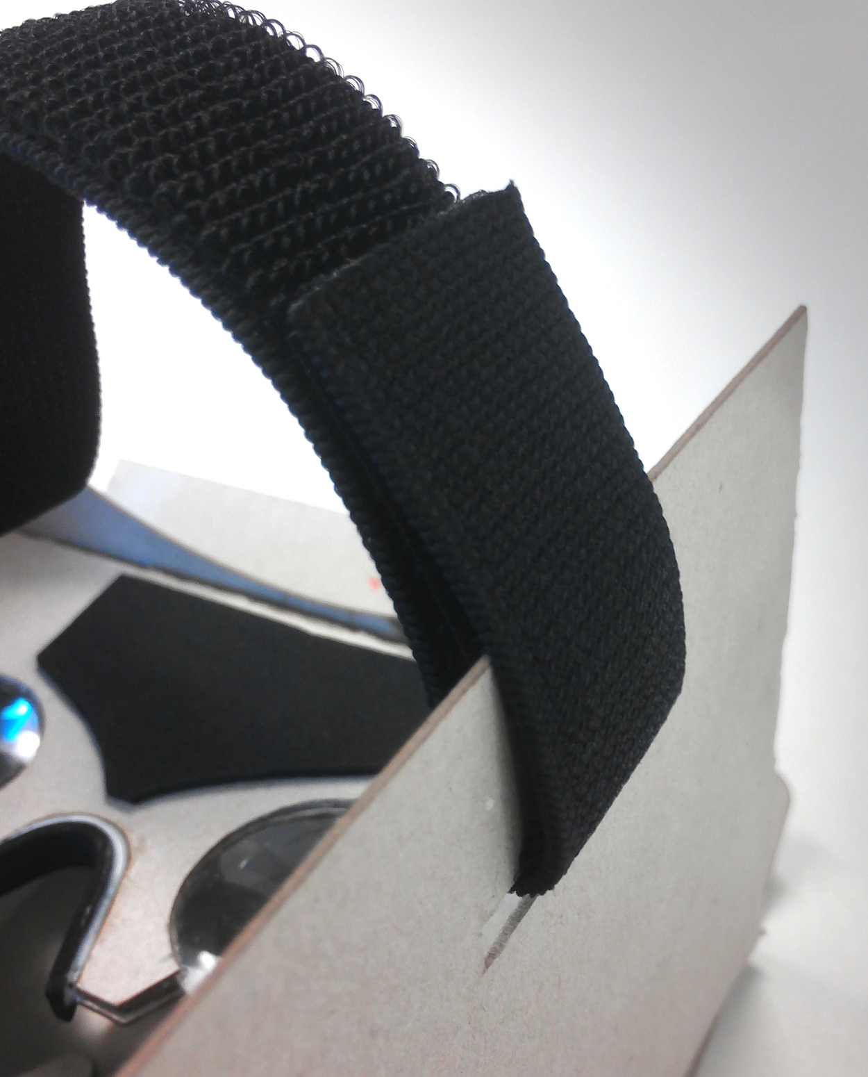
Figure 35: Attach the rubber band on the right side of the cardboard
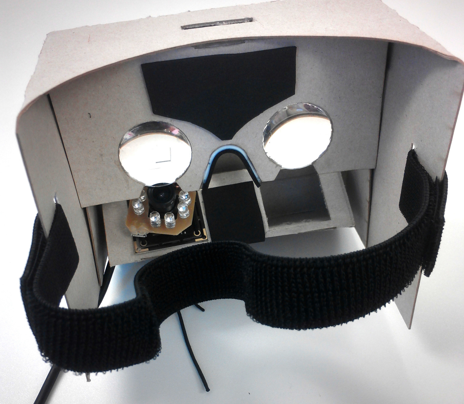
Figure 36: Cardboard with one attached Velcro rubber band
- Now take one Velcro rubber band attach one end to the left slot of the cardboard, as shown in figure 34. Then pull the other end of the Velcrorubber band though the right slot of the cardbard, as shown in figure 35. The result should looks like on the figure 36.
-
- Take the second Velcro rubber band and attach it’s end to the top slot of the card board, shown in figure 37. As final step take the other end and surround the first rubber band with the second, as shown in figure 38, to complete the head mount.
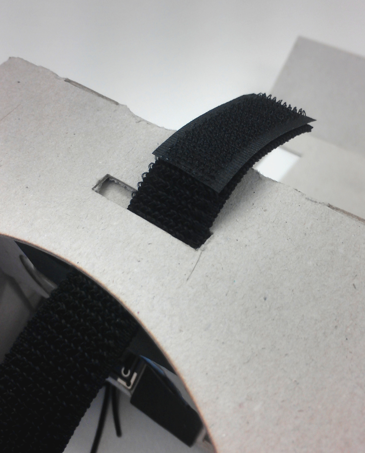
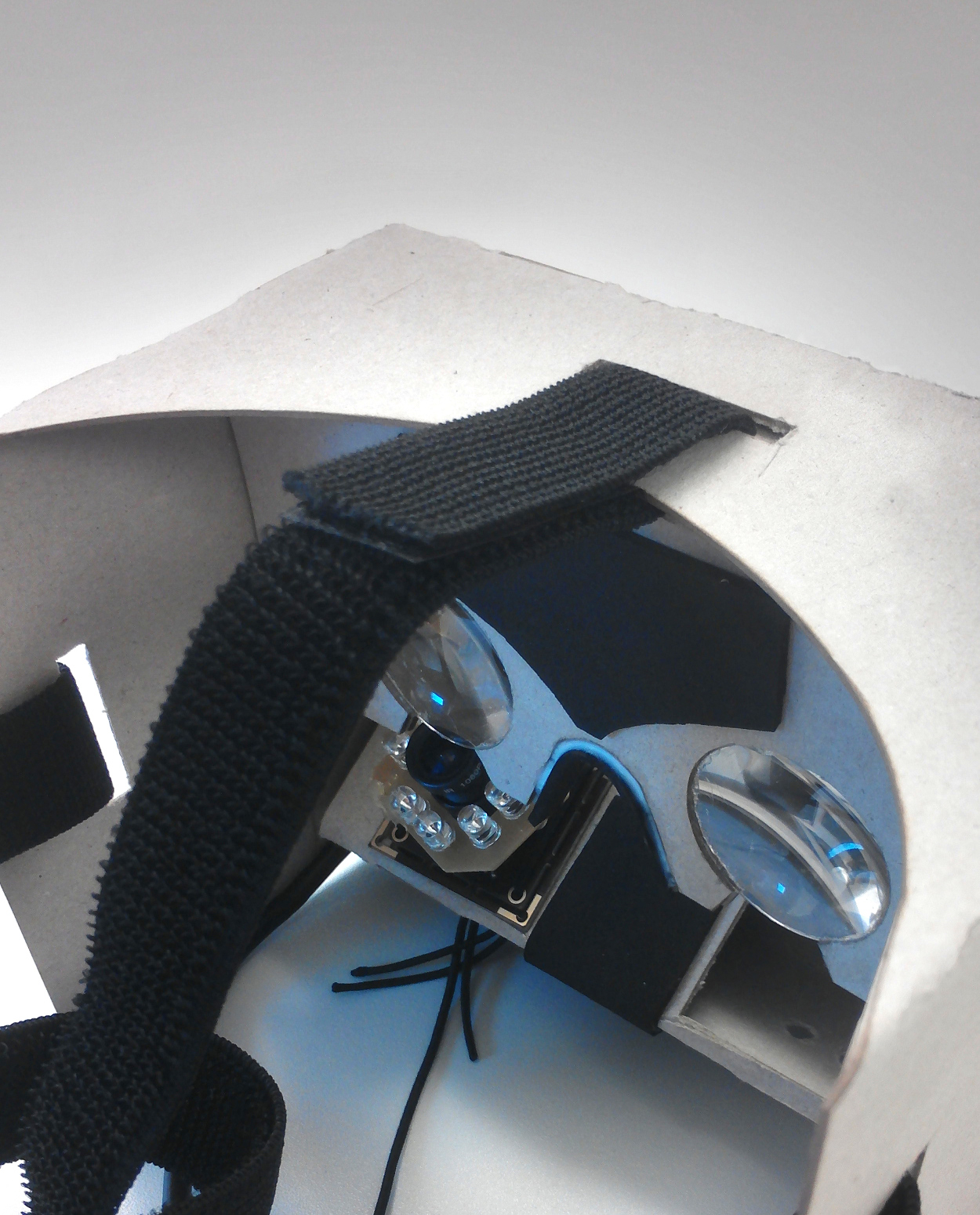
Figure 37: Attach the second rubber band to the top of the cardboard
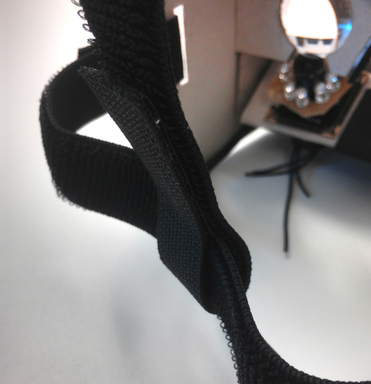
Figure 38: Attach the other end to the first rubber band
- Take the second Velcro rubber band and attach it’s end to the top slot of the card board, shown in figure 37. As final step take the other end and surround the first rubber band with the second, as shown in figure 38, to complete the head mount.
-
- As the next step take one male and one female Velcro tapes (see figure 39). Glue one tape on the top of the cardboard and it’s counterpart on the end of the flap of the cardboard, as shown in figure 40. It’s important that the position of both tapes have to match when the flap is closed, else the flap won’t stay closed.
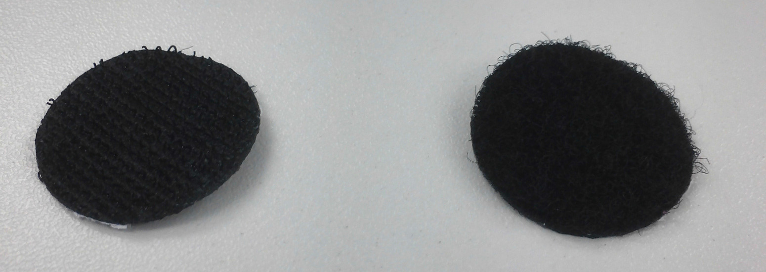
Figure 39: male (left) and female (right) Velcro tapes
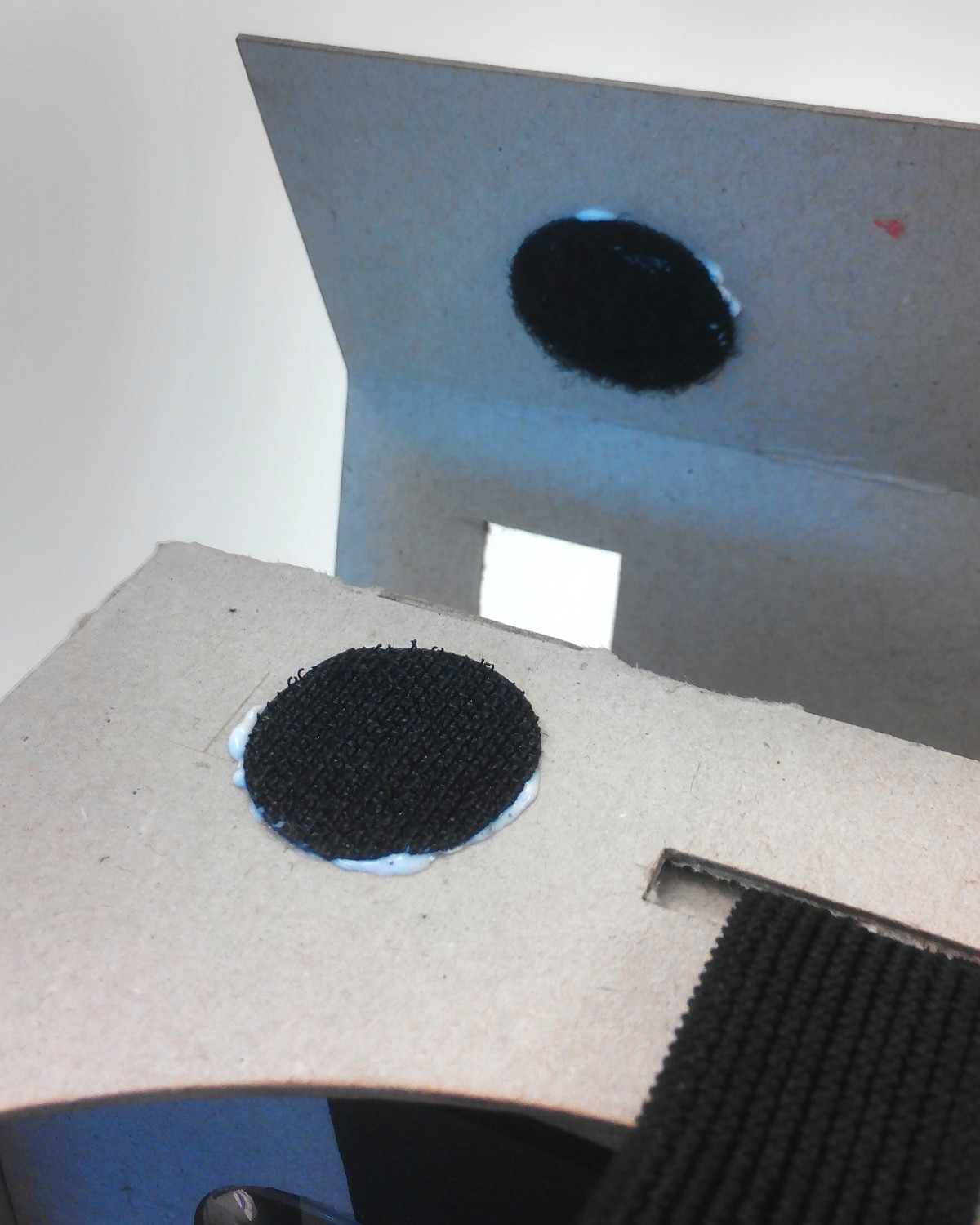
Figure 40: Glueing the tapes onto the cardboard
- As the next step take one male and one female Velcro tapes (see figure 39). Glue one tape on the top of the cardboard and it’s counterpart on the end of the flap of the cardboard, as shown in figure 40. It’s important that the position of both tapes have to match when the flap is closed, else the flap won’t stay closed.
-
-
- You can now take a 4-port USB-hub and insert it under part F inside the
flap of the cardboard, like shown in figure 41. The ports should look to the bottom. Finally, take (micro)USB cables to connect the camera and the circuit board with the hub.
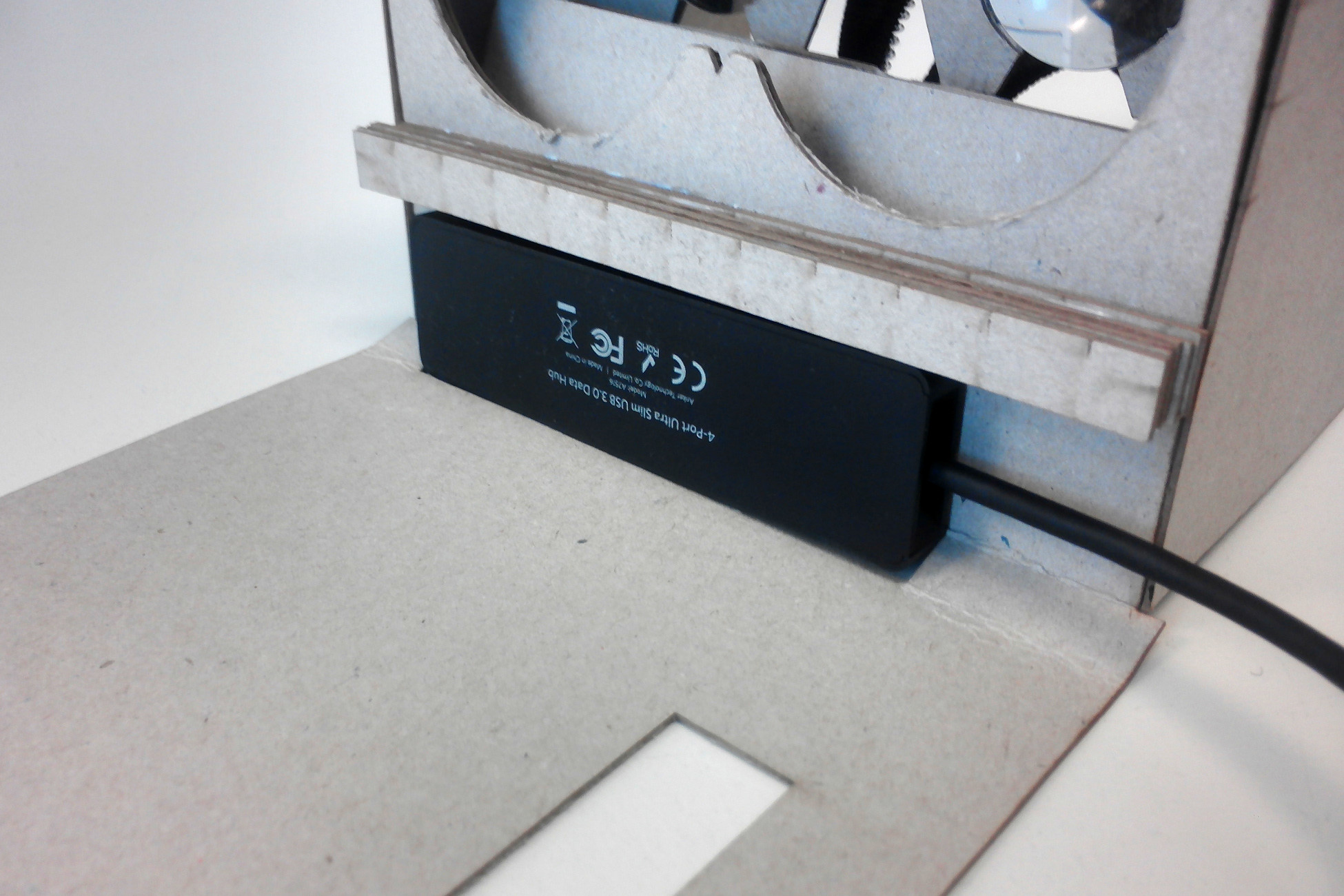
Figure 41: Position of 4-port USB-hub inside the flap
If you followed the guide correctly, you should now have a cardboard which looks like the one on the figure 42 and 43.
- You can now take a 4-port USB-hub and insert it under part F inside the
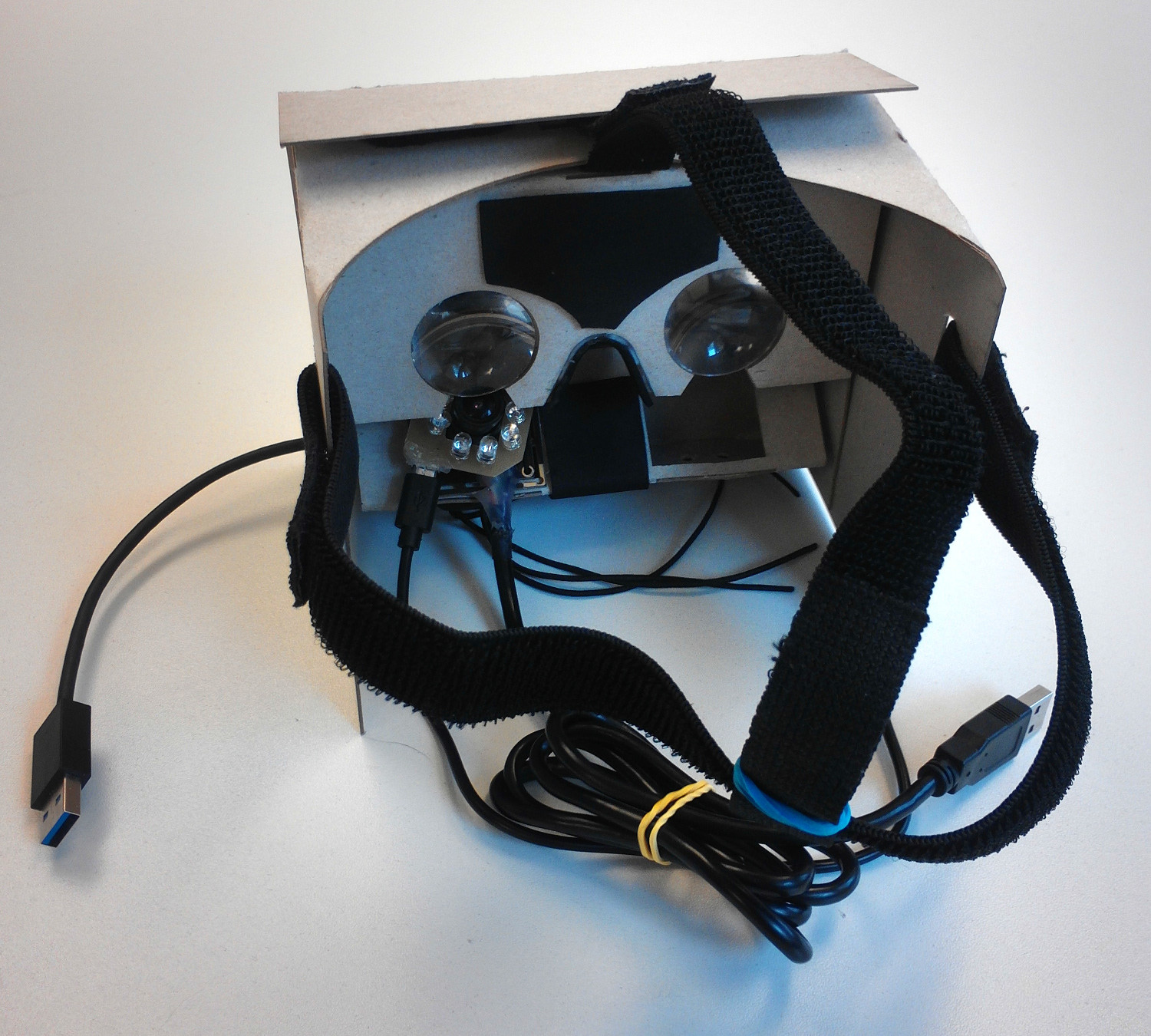
Figure 42:The inside of the resultant cardboard
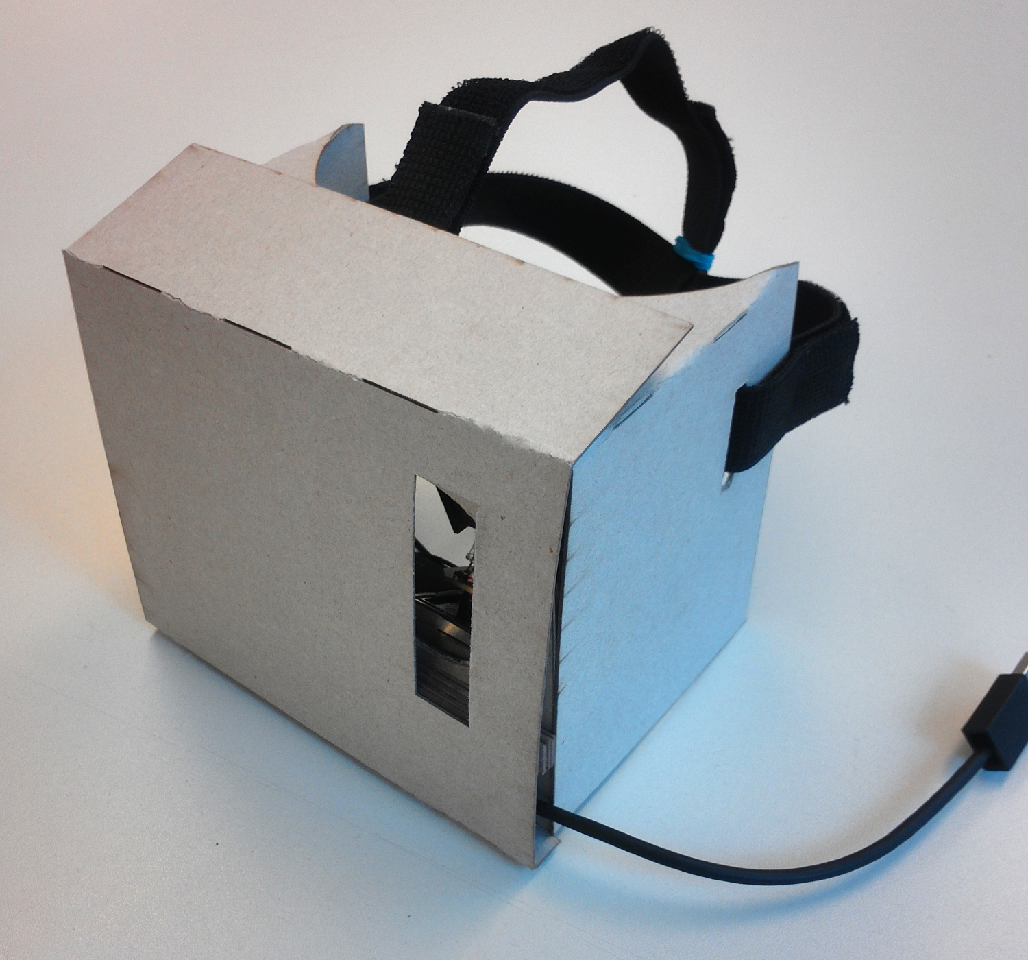
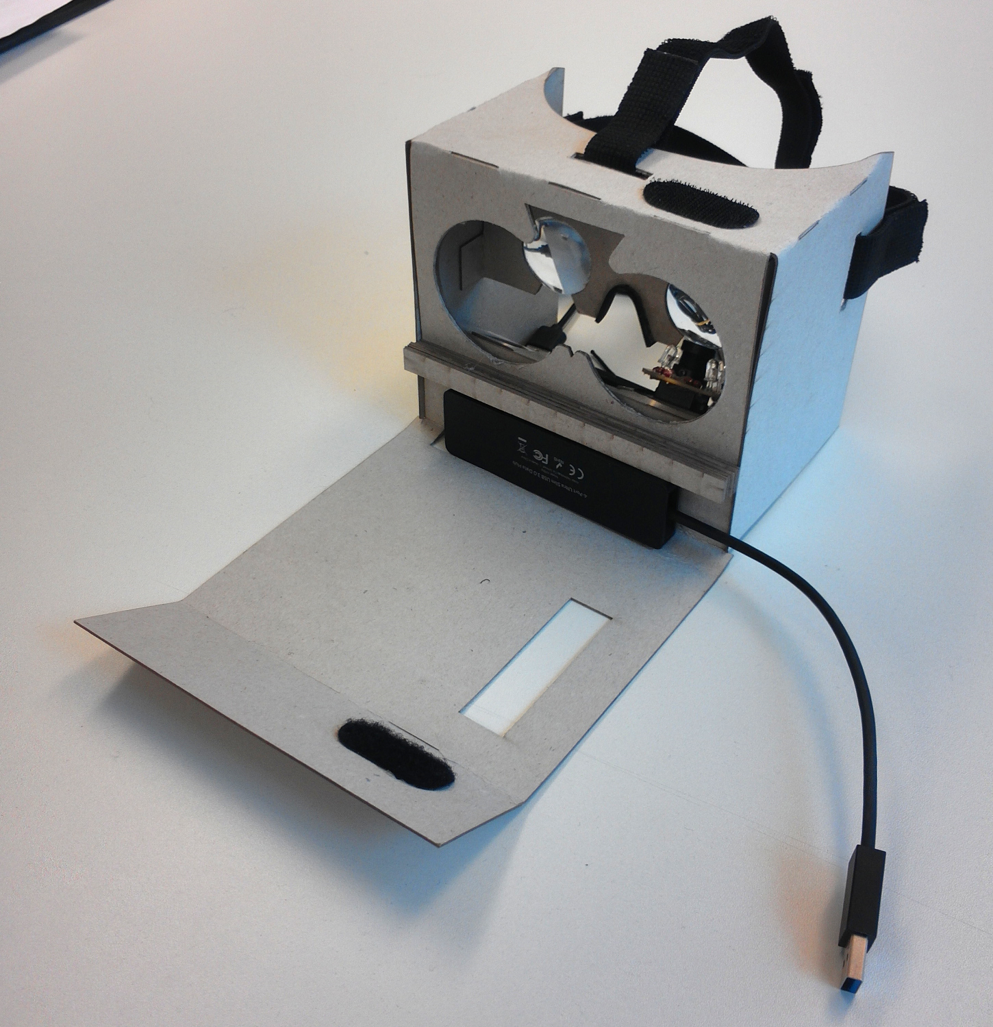
Figure 43: The outside of the resultant cardboard -